Cutoff Plane
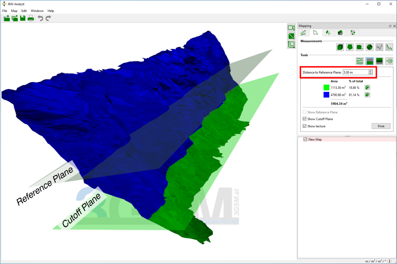
The Cutoff Plane is used to discriminate parts of the 3D model above and below the plane. The plane is parallel to the Reference Plane and has the same direction of the normal vector. The Cutoff Plane is activated by clicking the “Cutoff Plane”  icon in the toolbar of the Geometry tab of the Mapping pane. Different colours are assigned to the parts above and below the plane and the corresponding total areas (in m3) and relative areas (in %) are calculated.
The Geometry tab provides following information and configurations:
- Distance to Reference Plane: Defines the distance of the Cutoff Plane from the Reference Plane. It can be changed manually by entering the distance or by using the scrolling mechanism. Re-calculations of the areas are performed simultaneously by the software.
- Calculated area sizes: Displays the area sizes above and below the Cutoff Plane in m2 and percentage of the total area
- Show Reference Plane: Shows or hides the Reference Plane in the view
- Show Cutoff plane: Shows or hides the Cutoff Plane in the view
- Show texture: Activates or deactivates the texture of the 3D model
- Report: Prints a report which lists the available information and shows the corresponding picture of the 3D model
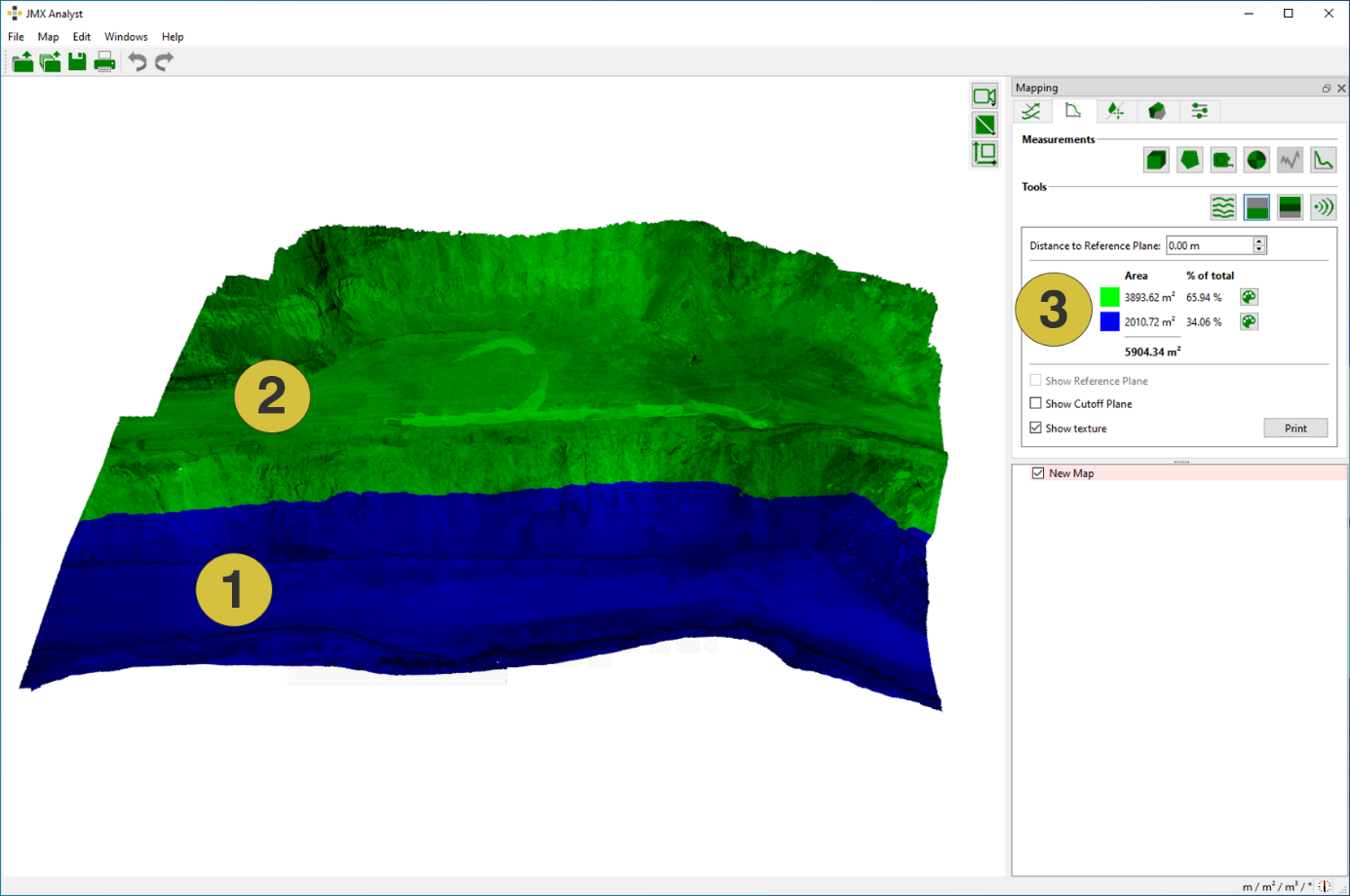
- Area below the Reference Plane
- Area above the Reference Plane
- Configuration and information display
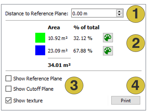
- Distance to Reference Plane
- Area partitioning
- Viewer options