Volume
Geometry Measurements i.e. Volumes, Tape, Measuring Points, and Sections, are managed in individual lists in the Geometry tab of the Mapping pane.
Analyst features the volume estimation of moulds delineated by a polygon on the 3D model. The Volume feature uses a user-defined polygon (area), the volume body is formed bases in the polygon and the interpolated with an uneven surface. The uneven surface closes the volume body with the interpolated surface and the 3D model surface.
Standard operating procedure
- Click on the “Volume”
 icon in the toolbar of the Geometry tab or use the shortcut key “V”
 - Draw an area on the 3D model by subsequently clicking on the 3D model with the left mouse button. The drawn area has the following properties:
- The area encloses the prospective volume body along the 3D model
- The area forms an artificial surface for closing the prospective volume body
- Finish the Volume measurement and continue the mapping by pressing the “Space” key or finish the Volume measurement by clicking “Enter” or by clicking the “Volume” icon. The calculated volume is provided instantly in an individual list in the Geometry tab.
Edit the Volume measurement by a double click with the right mouse button on the item:
- Insert a point by holding “Ctrl” and the right mouse button
- Delete a point by clicking “Alt” and the right mouse button
- Open the area by clicking “Alt” and the right mouse button and a click on the polygon
- Move a point by clicking “Shift” and the right mouse button
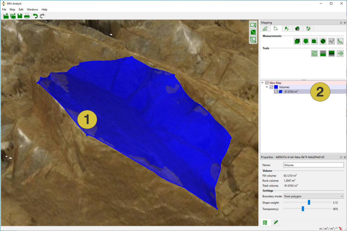
- Volume
- Value of total volume
The below figure shows the Properties pane for Volumes. The pane is activated in the context menu with “Show Properties” or by a click on “Windows | Properties” in the menu bar. It comprises:
- Name of the Volume
- Volume:
- Fill Volume: Volume enclosed by the area and 3D model lying in front of the 3D model (“in front of the rock mass”)
- Rock Volume: Volume enclosed by the area and 3D model lying behind the 3D model (“in the rock mass”)
- Total Volume: Calculated total volume (difference calculation between rock volume and fill volume)
- Settings:
- Boundary Mode:
- From clicked points: Artificial surface is calculated from the points clicked by the user on the 3D model. In case of “from clicked points, only the clicked points will from part of the interpolated surface, and lateral gaps are closed in direction of project from current view.
- From polygon: Artificial surface is calculated from polygon points along the 3D model. It is giving a more detailed set of points along the 3D model surface y sampling a dense set of points along the 3D model surface which is used for interpolation.
- Shape Weight: The slider is used to change the shape of the artificial surface. The interpolation surface is formed from a "median plane". The Shape weight is a weight on the points used for interpolation and it affects a kind of zone of influence of each point and thus governs the deviation from the median plane. If the weight is set to 1, then the points have only a small zone of influence and appear as "spikes" from the median plane, while if you increase the shape weight the zone of influence of each point increase and the interpolation surface becomes smoother and undulating.
- Transparency: The slider is used to change the transparency of the volume annotation
- Boundary Mode:
The name of the Volume can be edited in order to use an intuitive name or for more detailed descriptions. Customized notes can be added to individual Tapes in the Notes  tab.
tab.
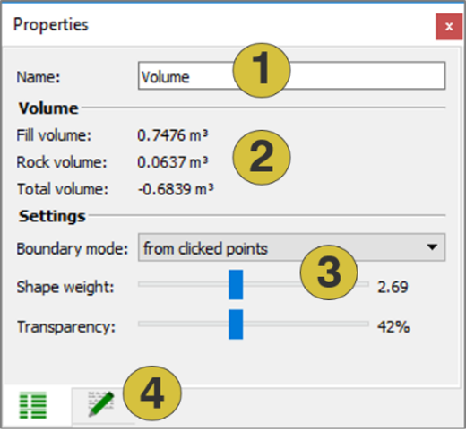
- Name of the Volume (editable)
- Calculated volume
- Settings (editable)
- Notes (editable)
Context menu
- Edit
Insert a point by clicking “Ctrl” and the right mouse button. Delete a point by clicking “Alt” and the right mouse button. Open the area by clicking “Alt” and the right mouse button and a click on the polygon. Move a point by clicking “Shift” and the right mouse button. - Set Colour
Defines a new colour for the Volume - Active
Activates (shows) and deactivates (hides) the selected item - 3D View-dependent Redraw
Redraws the Volume in subject to the current view - Look at
Centers the Volume in the 3D viewer - Look at and Zoom
Centers and zoom the Volume in the 3D viewer - Delete
Deletes the selected Volume - Show Properties
Opens the Properties pane - Export
- Export as DXF Exports the measurement as ”.dxf” file
- Export as VRML Exports the measurement as ”.vrml” file