Support Designer
The Support Designer is an automated optimization tool that enables engineers to obtain cost-effective support layouts that meet stability requirements. For defined support designer regions, users can specify the design parameters to optimize, including support spacing, length, angle, and capacity (tensile, connection, and bond strength). This capability complements the existing Compute function by offering design optimization for a scenario.
Add Support Designer Region
Support Designer Regions can be created by selecting:
- Support > Support Designer > Add Support Designer Region

How the region works:
The support designer regions will snap to the external and should specifically be applied to the area of interest for adding a support pattern. Once the start and end point along the external is defined, a dialog will appear to select which support type should be used for the pattern in that region.
- Only End Anchored, Geosynthetic, Soil Nail, and Grouted Tieback support types will be allowed to be assigned to these regions
- A maximum of one region is allowed on the model
- The right-click menu will have options to edit or delete the assigned geometry and edit the assigned property
Support Designer
The Support Designer can be opened by selecting:
- Support > Support Designer > Support Designer…

Define Global Design Requirements
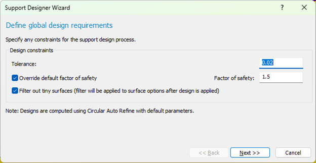
Design Constraints are available to better calibrate the potential solution:
- Tolerance controls the convergence precision for optimization (e.g., 0.01); smaller values mean more precise results but longer runtime
- Override default factor of safety allows users to specify a custom minimum factor of safety target instead of using the default of 1
- Filter out tiny surfaces will make sure that the design is based on results that do not have an insignificant area, and will apply a filter to the minimum area filter in the Surface Options when the design is applied
Define Support Parameters
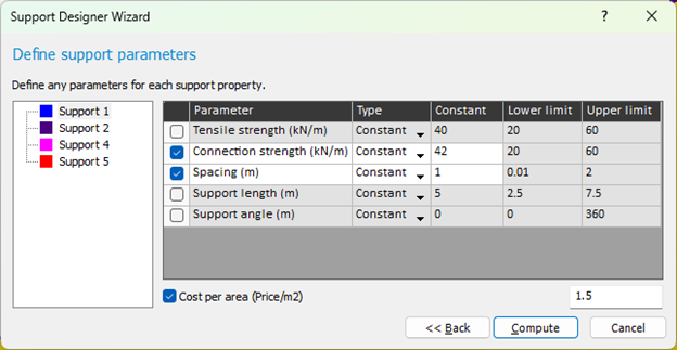
Optimization Parameters
Optimization settings can be configured for each support type in the model. Users can choose between supports (which have already been defined in Properties > Define Support) in the left panel and define how each optimizable parameter should be handled.
The following parameters can be optimized (selected using checkboxes) for each support:
- End Anchor
- Anchor Capacity
- Spacing
- Support length
- Support angle
- Geosynthetic
- Tensile Strength
- Connection Strength
- Spacing
- Support length
- Soil Nail & Grouted Tieback
- Tensile capacity
- Bond strength
- Spacing
- Support length
- Support angle
- Support angle is measured counterclockwise from the positive x-axis.
- If a support is from the manufacturer library, values set from the library will not be available to be optimized.
Optimization type can be either:
- Range: Parameter will be optimized within specified lower and upper limits (e.g., tensile strength between 50-150 kN/m)
- Constant: Parameter remains fixed at a specified value and won't be optimized
Users can specify the cost (per area/per support) for each support.
Clicking the Compute button will close the dialog and open the support designer engine which will show progress while the design is being calculated.
Properties assume default values when they are not selected for optimization; defaults are assigned as follows:
- Anchor capacity / tensile strength / connection strength / bond strength: Uses the existing property of the assigned support
- Length: 5 units (depends on model units)
- Spacing: Approx. 1 unit (depends on model units)
- Angle: Horizontal
Preview and Apply Results
After the support designer engine finishes computing, the results will be available by selecting:
- Support > Support Designer > Support Designer Results

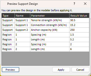
Users can preview designs in a table format showing support types, optimized parameters, stability, and cost.
- Cost per unit width for the designs will only be output if the user has defined a cost per area / per support for each of the support types in the wall.
- The Preview button allows the user to visualize the layout in the viewport
- Once satisfied, click Apply to update the model. Note that if support capacities are optimized, applying the design will modify support properties to match the optimized values.
Error Reporting
If error messages are generated during computation, you can view them by going to:
- Support > Support Designer > View Error Messages
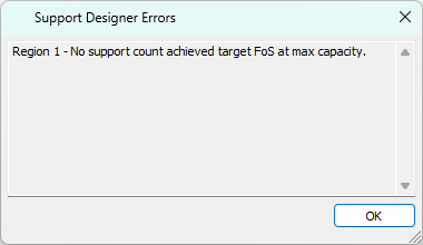
Users can see any error messages generated during support design computation and modify their inputs accordingly.