Reinforcement
What does "Show Support Forces" do?
When using this option, the distribution you are seeing is not the force in the nail. It is the nail force diagram which gives you the support force distribution. This is the stabilizing force added to the limit equilibrium equations due to the support.
So for each point along the support, the force at this point is equal to the capacity of the nail if the failure surface went through this point. A description of nail force diagrams can be found in the Overview of Support Implementation topic of the online help.
To get the load distribution within the support, you'd need to use a finite-element program that computes deformation, like RS2. The other option, which is not as accurate, is to look at the mobilized force in the nail by looking at the Slice view (see image below). This is the force in the support (per unit distance out of plane) if you were to reduce the strength in the soil mass by the factor of safety. A quick measure is to take this force and divide it by the factor of safety. If the factor of safety is one, then the support is in a state of equilibrium.
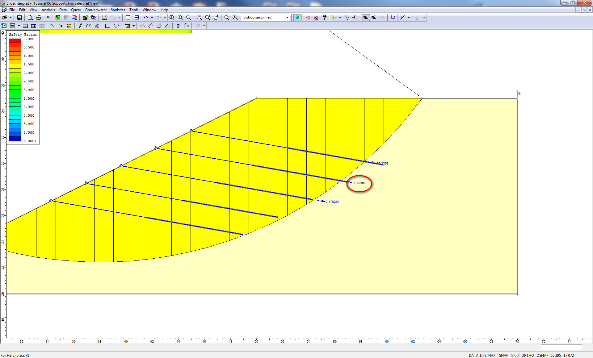
The units are Force in the nail force dialog (kN metric, lbf imperial), and are per unit distance out of the plane. So they will change depending on the out-of-plane spacing of the support. To get the force in an individual bolt, you have to multiply the force number from the slice data by the spacing. So in the figure above, the bolt force is 9.2kN, and the spacing is 2m. So the actual force in the bolt is 18.4kN. If the FS=1.5, then the true force in the support is 18.4/1.5=12.3kN.
What properties should I use for geogrid and geotextile reinforcement?
Tensile strength is published by the manufacturer. The only issue is whether you use ultimate or allowable tensile strength. A good reference for ultimate versus allowable strength for support in slope stability analyses can be found in Duncan and Wright's Soil Strength and Slope Stability text. Chapter 8 in particular deals with support.
In the text, Method A is the same as Slide2's Active model, while Method B is the same as Slide2's Passive method. Wright and Duncan suggest that one should use the allowable capacities for Method A, and suggest ultimate capacities for Method B.
As far as shear strength is concerned, you may want to start off with the linear model. This is straight Mohr-Coulomb behaviour and is what most people use. When dealing with adhesion and friction angle, this is the shear strength of the interface between the soil and the geotextile. This is discussed in the attached document. What people generally do is take a percentage of the soil strength in which the geotextile resides. This is called the interaction coefficient. The interaction coefficient is simply a factor that is applied to the tangent of the friction angle of the material in which the geosynthetic is embedded. See page 7 of the attached document. Basically, it's a shear strength reduction factor. To use an interaction coefficient (Ci), set:
Adhesion = cohesion*Ci
Friction angle = arctan(Ci*tan(phi))
Cohesion and phi are the Mohr-Coulomb parameters of the soil in which the geosynthetic is embedded. If the geosynthetic is in more than one material, use the material-dependent option for support.
Click here to view the Geosynthetics for Slope Reinforcement pdf.
How is soil nail capacity computed when both tension and shear options are selected?
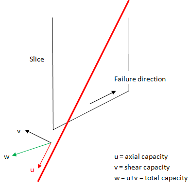
Slide2 computes a support force vector for tensile failure and for shear failure independently of each other. It then adds the tensile force vector to the shear force vector to get a total support force vector. Note that this vector has both magnitude and direction, and therefore you cannot simply add the nail force diagrams together. Since the shear force acts in a different direction to the tensile force, you end up with a resultant vector. Slide2 shows the magnitude of this resultant vector in the nail force diagram for shear and tension.
For more information, see the Soil Nail section of the Online Help.
Can pre- or post-tensioning be modelled in Slide2?
There is no way to put a pre-/post-tensioning force into Slide2. Since Slide2 is a limit-equilibrium program, all support is modelled as simple force being put back into the system to stabilize the slope. The magnitude of this force depends on the capacity of the bolt against tensile, pullout or stripping failure mechanisms.
Ultimately, each support element in Slide2 only applies a single force to the sliding mass, using either the Active or Passive assumption. Please review the Overview of Support Implementation help topic for more information.
How can I model stone columns in Slide2?
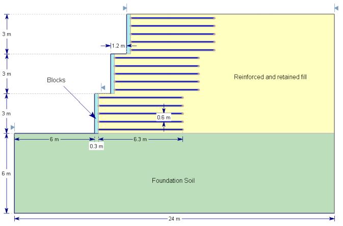
Many customers model stone columns in Slide2 by defining a material unit with the shear strength properties of the stone. MSE wall examples can be found in the Verification Manual. In particular, verification models #87-94 deal with block walls. It’s a similar approach to a stone column.

How can I model a gabion wall (or retaining wall) in Slide2?
For gravity walls such as gabions or rockeries, we suggest using material layers with material properties equivalent to the material making up the walls. For examples of MSE walls, see Examples #87-94 in the Slide2 Verification Manual.
For modelling the actual retaining wall material, the user basically has two choices. Infinite strength, in which case this forces all failure surfaces below the wall. Concrete, in which case a failure surface can go through or under the wall. The only issue then is the shear strength of concrete.
The modelling of the concrete really depends on the state of stress applied to the concrete. The shear strength of the concrete/shotcrete depends very much on the unconfined compressive strength and age of the concrete and there are a variety of methods/codes that structural engineers use to relate them. For example, if the allowable shear stress for unreinforced concrete is around 0.17 x sqrt(f'c), for 20MPa (3000psi) concrete, the shear strength is 0.75MPa (100psi). Under low stress, this shear strength could be used as the cohesion with zero friction since at low normal stress, the resulting increase in strength due to friction has little effect on the overall strength.
What input parameters should be used for pullout adhesion for geotextiles?
The following is a good reference for the evaluation of geotextile interface properties:
Farrag, K., and Morvant, M. J. (2004). Evaluation of Interaction Properties of Geosynthetics in Cohesive Soils: Lab and Field Pullout Tests. Louisiana Transportation Research Center. FHWA/LA.03/380.
On page 74 (Evaluation of Pullout Coefficients) there is a series of equations. Equations 3, 4, and 5 are basically what Slide2 uses. In equation 5, Ca is the soil adhesion that Slide2 asks for, and delta is the friction angle. If you look at equation 8 in the above report, you’ll see the definition of alpha and F* and how they relate to pullout resistance. In comparing this equation to equation 5, you’ll see that you can equate the two equations. If you have alpha and F*, set the soil adhesion to zero and the friction angle = invtan(alpha*F*).
These equations are also defined in the Geosynthetic topic.
How can I model a sheetpile wall in Slide2?
There are a few different ways to model a sheetpile wall in Slide2. If you want to model the global failure of a surface below the sheetpile wall, a thin material layer with infinite strength is suggested. This will force the failure surfaces to go below the wall.
If you are modelling failure through the wall, then you can model the wall as a pile/micropile support element or a material layer. See the Pile / Micro Pile help topic for more information.
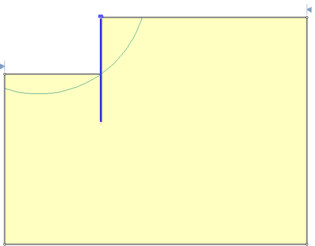
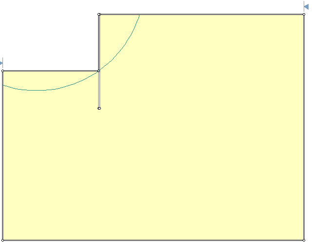
See below two models of the same slope. In one case the pile is modelled with a support element, and in the other case, a material layer is used. In the model piles with 0.2 m2 area, spaced at 1m, are assumed. This gives a pile material thickness of 0.2m if the pile wall is modelled as a material. If the spacing is different, the thickness of the pile material also needs to be adjusted. For example, if the spacing was 2m, then the pile wall thickness would be 0.1m. The results for the two models are quite close.
You can also refer to Example #49 in the Slide2 Slope Stability Verification manual. All example files are installed with the Slide2 program.
What strength should be used when modelling piles in Slide2?
If you are modelling failure through the wall, the issue then becomes what you use for the shear strength (material) or shear force capacity (micropile). If the mode of failure is assumed to cause rupture of the wall itself, then you can use the shear strength of the wall material. This is usually something like the tensile capacity of the steel or joints but often there are codes for these types of numbers. If failure is assumed to create a passive type bearing failure of the toe material, then this strength should be used. Often people will use the passive resistance (F=Kp*gamma*H*H/2), RSPile, or another program to determine the strength of piles assuming the failure surface intersects the pile at a certain location.
The following reference describes the aforementioned analysis for soil nails:
Forest Service Engineering Staff (1994). Application Guide For Launched Soil Nails, United States Department of Agriculture. EM 7170-12A.
How can I model a continuous sheet pile system? How should I deal with the pile/micropile "spacing" input parameter in this case?
What you need to determine is the shear force that the support will contribute.
If you use a material layer, then you need to determine the appropriate thickness based on the material strength. In the example attached to this article, the pile material's cohesive strength is 300kPa. With a material thickness of 0.2 intersected by the slip surface the support is contributing 60kN of shear, per unit out of the plane. This is the same as defining a micropile with a shear strength of 60kN and a spacing = 1 meter, as you can see in the "pile passive" file. In the case of the micropile, Slide2 does not need any thickness, only the input shear strength is considered.
For modelling a simple sheet pile wall using micropiles, the "spacing" of the micropiles is a fictitious number. We use a spacing of 1 for simplicity, and then enter a value of micropile shear strength which gives the equivalent shear strength per unit out of plane, as the sheet pile wall of a given thickness.
Remember that the Slide2 analysis is 2-dimensional, and support forces are averaged over the unit out of plane distance, regardless of how you model the support.
What does the Support Force Graph show?
It is a common misconception that the pile/support force diagrams are soil/pile interaction forces. Slide2 does not give soil/pile interaction forces, and RS2 is required in order to do that. The hatched figure is simply the pile force diagram drawn on the side of the pile.
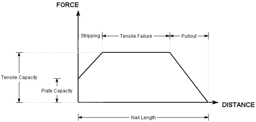
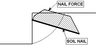
Soil Nail Force Diagrams
For an overview of how the pile/support force diagrams are determined, see the Overview of Support Implementation help topic.
Active vs Passive Support
Many users ask whether Active or Passive support should be used, and what capacities should be used. First, it is important to identify the main difference between Active and Passive support implementation in Slide2. Basically, active support forces work to reduce the driving forces in the factor of safety calculations, while passive support forces work to increase the resisting forces.
In terms of convergence properties, it has been found that active support is generally better. However, in the end, it is up to the user to determine what type of support makes the most sense in each situation.
Another good reference for support in slope stability analyses can be found in Duncan and Wrights Soil Strength and Slope Stability Text, the reference for which is provided below:
Duncan, J.M. and Wright, S.G. (2005). Soil Strength and Slope Stability, John Wiley and Sons Inc.
In particular, Chapter 8 deals with support. In Chapter 8 of the Duncan and Wright text, Method A is the same as Slide2’s Active support model, while Method B is the same as Slide2’s Passive support model. This reference offers the following guidelines:
For Active support (Method A), because the support forces are included in the denominator of the safety factor equation (Eqn.1) the support force is NOT divided by the factor of safety calculated during the analysis. Only the soil strength is divided by the factor of safety. Hence the support capacity input by the user for Active (Method A) should be the ALLOWABLE support force.
For Passive support (Method B), because the support forces are included in the numerator of the safety factor equation (Eqn.2) the support forces ARE divided by the factor of safety calculated during the analysis (i.e. both soil strength and support forces are divided by the factor of safety). Hence the support capacity input by the user for Passive (Method B) should be the ULTIMATE support force.
According to Duncan and Wright (2005), Method A is preferable, because the soil strength and the reinforcement forces have different sources of uncertainty, factoring them separately makes it possible to reflect these differences. The allowable support force (Method A) allows the user to choose an acceptable safety factor for the support capacity in advance, and this determines the value (e.g. tensile strength) which is input into the Support Properties dialog.
For either active or passive support methods, the long-term capacity of the support should be considered if long-term slope stability is important. The long-term capacity of reinforcement may depend on several factors including creep characteristics, installation damage, durability and other factors.
In the case of active support, how are the normal and shear components proportioned when they get to the base of the slices?
The active force due to support is applied as a force to the slice base it intersects in the same way as any external force is applied. The magnitude of the force comes from the nail force diagram as described in the Online Help and the position of the force is the point of intersection with the base of the slip surface. This force is then resolved into effective normal and shear forces for input into the limit-equilibrium equations. The force is not distributed in any way through the soil or adjoining slices.
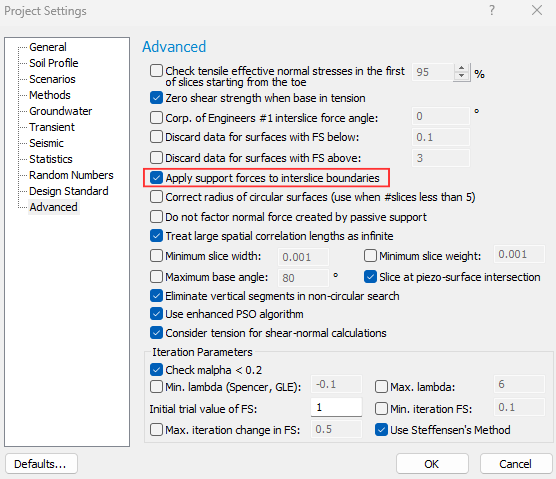
There is, however, an advanced option (see image below) for spreading the support force over the slices in which it intersects.