Show Line of Thrust
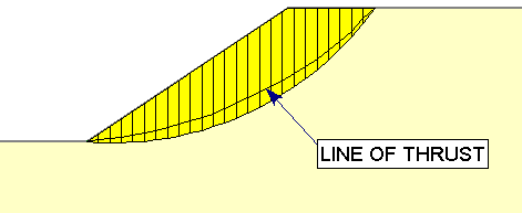
The Show Line of Thrust  option in the toolbar or the Query menu, will toggle the display of the line of thrust, for queried slip surfaces.
The thrust line gives the location of the resultant interslice forces. It is computed by summing the moments of all forces acting on an individual slice about the center of the base of the slice. These forces include the interslice, external, seismic, and support forces. Wedge weight, base normal and shear forces are not used since they pass through the center of the slice base.
Since the location of the thrust line is known at both the first and last slice, the thrust line is computed by starting at both ends of the sliding mass and working towards the center slice. The location of the thrust line on the first and last slice will also take into account the existence of hydrostatic water forces due to ponded water and water in tension cracks. The thrust line for the center slice is computed as an average of the locations computed from traversing from the two ends.
Display of thrust line for circular slip surface

The Line of Thrust is calculated and can be displayed for the following analysis methods in Slide2:
- Spencer
- GLE/Morgenstern-Price
- Corps of Engineers #1
- Corps of Engineers #2
- Lowe-Karafiath
The Line of Thrust is NOT calculated, and cannot be displayed, for the following analysis methods:
- Ordinary/Fellenius
- Bishop Simplified
- Janbu Simplified
- Janbu Corrected