Add Tension Crack
A Tension Crack zone can be defined in Slide2 by adding a Tension Crack boundary, above which a tension crack zone will exist.
To add a Tension Crack boundary to your model:
- Select Add Tension Crack
 from the toolbar or the Boundaries menu.
 - Enter the vertices of the Tension Crack boundary as described in Entering Coordinates.
- When all vertices are entered, right-click and select Done, or press Enter with nothing in the prompt line.
- The region above the Tension Crack boundary, and within the External Boundary, will then be shaded with a vertical line pattern, to highlight the Tension Crack zone you have created (i.e. a Tension Crack boundary defines the lower limit of a Tension Crack zone).
In Slide2, only ONE Tension Crack boundary can be defined for a model. After a Tension Crack is added, the Add Tension Crack option is disabled. If you want to add a completely new Tension Crack, then you must first delete the existing Tension Crack with the Delete Boundary option, and then add a new Tension Crack boundary.
Tips
- By default, when a Tension Crack boundary is initially added to the model, the Tension Crack zone is defined as being Dry (not water-filled). This can be changed at any time, using the Define Tension Crack option in the Properties menu. The Define Tension Crack option allows you to define the water level in the Tension Crack zone as dry, water-filled or partially water-filled.
- Unlike a Material Boundary, a Tension Crack boundary does not have to intersect the External Boundary in order to form a closed region.
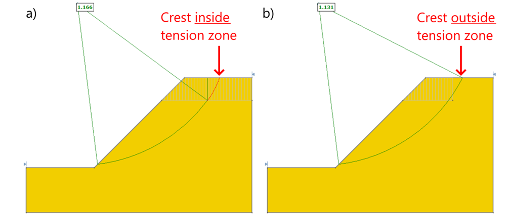
- Note that the crest of a slip surface must be contained within the tension crack zone in order for the slip surface to be truncated. For example, the circular slip surface in the below figure is clipped only if its crest is located inside the tension zone (case a). Otherwise, it will not be truncated (case b).
- If a slip surface intersects into and out of the tension crack zone more than once, then it is only truncated to the first region from the crest.
- The theoretical maximum tension crack depth can be estimated as described below.
Theoretical Maximum Tension Crack Depth (z)
For a given soil with Mohr-Coulomb strength parameters c and f, and unit weight ![]() , the theoretical maximum tension crack depth z can be estimated from the following equations:
, the theoretical maximum tension crack depth z can be estimated from the following equations:
