End Anchored
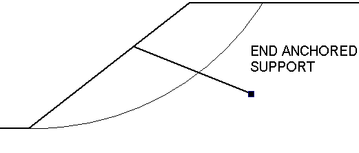
The End Anchored support type allows you to model a simple end anchored support system, such as mechanically end anchored rock bolts, or deadman anchors.

Anchor Capacity
The Anchor Capacity entered for an End Anchored support type, represents the maximum load which an individual anchor can sustain before failure. Generally, this will be the pullout or failure load of the anchoring mechanism, however, it could also be the tensile strength of the anchor, or the strength of the plate assembly on the slope surface, if either of these capacities are less than the failure load of the anchoring mechanism.
Out of Plane Spacing
The spacing between soil nails in the out-of-plane direction (i.e. along the slope), measured from center to center.
Force Application
For End Anchored support, the default method of Force Application = Active, because some tensioning of the anchors is usually applied. See the Force Application topic for a discussion of the significance of Active and Passive support force application in Slide2.
Force Orientation
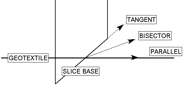
When the support begins to take on load, due to displacements within the slope, the direction of the applied support force can be assumed to be:
- Tangent to Slip Surface
- Bisector of Parallel and Tangent (i.e. at an angle which bisects the tangent to slip surface orientation, and the parallel to reinforcement orientation)
- Parallel to Reinforcement
- Horizontal
- User-Defined Angle (i.e. the user may specify an angle, measured from the positive horizontal direction)

Implementation of End Anchored Support in Slide2
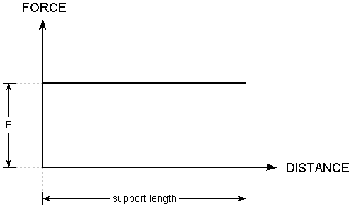
With the End Anchored model, the load applied to the sliding mass will be constant, regardless of where a slip surface intersects the length of the support. The applied load, PER UNIT WIDTH OF SLOPE, is simply equal to the Anchor Capacity divided by the Out of Plane Spacing. i.e.
F = T / S
where:
T = Anchor Capacity
S = Out of Plane Spacing
The Force Diagram for an End Anchored support type, is simply a horizontal line, representing a constant value of applied force, regardless of where a slip surface intersects the support.

Force diagram for End Anchored support