Grouted Tieback with Friction
The Grouted Tieback with Friction support type in Slide2, uses the same input parameters as the Grouted Tieback support type, with the following important difference:
- The Grouted Tieback with Friction support type allows you to account for the frictional strength (stress-dependent) of the soil/grout interface.
The Shear Strength properties of the soil/grout interface of the Grouted Tieback with Friction support type are described below. For a description of all other input parameters, see the Grouted Tieback support topic.
Pullout Strength
The Pullout Strength options for the Grouted Tieback with Friction support type:
- Adhesion
- Friction Angle
- Material Dependent Pullout Strength
- Shear Strength Model
are the same as described for the Geosynthetic support type. For a description of these options, see the Geosynthetic support topic.
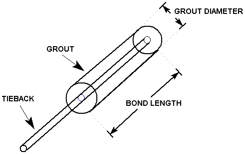
The area on which the shear force acts, for the Grouted Tieback with Friction support type, is defined by the Grout Diameter as described below.
Grout Diameter
The Grout Diameter for the Grouted Tieback with Friction support type, serves the following purpose:
- Assuming a symmetric, circular annulus of grout around the tieback Bond Length, the Grout Diameter is used to calculate the outer circumference of the grout annulus:
Circumference = 3.14159 * Grout Diameter
- The Circumference is then multiplied by the Bond Length for an anchor, to determine the surface area of the grout/soil interface, on which the shear force can act:
Area = Circumference * Bond Length

- The shear strength along the grouted length, is calculated from the Adhesion, Friction Angle and Shear Strength Model.
- The normal stress which is calculated along the bonded length, is assumed to be uniformly distributed around the grout annulus, and is also assumed to be equal to the vertical stress. The vertical stress is determined from the weight of soil overburden, and also the vertical component of any external loading.
- The cylindrical surface area is then multiplied by the shear strength along the bonded length, in order to obtain the maximum shear force which can be generated by pullout (or stripping) of the grouted tieback (see below for equations).
Implementation of Grouted Tieback with Friction Support in Slide2
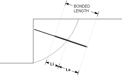
Consider a grouted tieback which intersects a slip surface, as shown below.

Li = bonded length of tieback within sliding mass
Lo = bonded length of tieback embedded beyond slip surface
Tieback (with Friction) Parameters
T = Tensile Capacity (force)
P = Plate Capacity (force)
![]() = Interface Friction Angle (deg)
= Interface Friction Angle (deg)
a = Interface Adhesion (force / area)
D = Grout Diameter
S = Out of Plane Spacing
At any point along the length of the tieback, there are 3 failure modes which are considered:
- Pullout (force required to pull the length Lo of the tieback out of the slope)
- Tensile Failure (maximum axial capacity of the tieback tendon)
- Stripping (slope failure occurs, but tieback remains embedded in slope)
The maximum force which can be mobilized by each failure mode, PER UNIT WIDTH OF SLOPE, is given by the following equations:
Pullout: ![]() Eqn.1
Eqn.1
Tensile: ![]() Eqn.2
Eqn.2
Stripping: ![]() Eqn.3
Eqn.3
If the Strength Model = Linear (Mohr-Coulomb), then the shear strength ![]() in Equations 1 and 3, is given by:
in Equations 1 and 3, is given by:
![]() Eqn. 4
Eqn. 4
If the Strength Model = Hyperbolic, then the shear strength ![]() in Equations 1 and 3, is given by:
in Equations 1 and 3, is given by:
![]() Eqn.5
Eqn.5
where ![]() is the normal (effective) stress along the Grout / Soil interface. If pore pressure is considered, the Adhesion and Friction Angle parameters are for effective stress conditions.
is the normal (effective) stress along the Grout / Soil interface. If pore pressure is considered, the Adhesion and Friction Angle parameters are for effective stress conditions.
See the Geosynthetic support topic for more information about the Linear and Hyperbolic shear Strength Models.
At any point along the length of the tieback, the force which is applied to the slip surface is given by the MINIMUM of these three forces (Tensile, Pullout or Stripping).
Applied Force = min (F1, F2, F3) Eqn.6
The Force Diagram for the Grouted Tieback with Friction support type can have the same general shape as described for the Grouted Tieback support type. See the Grouted Tieback support topic for an illustration.