Generalized Hoek-Brown
The Generalized Hoek-Brown strength criterion is described by the following equation:
where:
mb is a reduced value (for the rock mass) of the material constant mi (for the intact rock)
s and a are constants which depend upon the characteristics of the rock mass
σci is the uniaxial compressive strength (UCS) of the intact rock pieces
σ'1 and σ'3 are the axial and confining effective principal stresses respectively
In most cases it is practically impossible to carry out triaxial or shear tests on rock masses at a scale which is necessary to obtain direct values of the mb, s and a parameters in the Generalized Hoek-Brown equation. Therefore some practical means of estimating the material constants mb, s and a is required. According to the latest research, the parameters of the Generalized Hoek-Brown criterion [ Hoek, Carranza-Torres & Corkum (2002) ], can be determined from the following equations:
where:
- GSI is the Geological Strength Index
- mi is a material constant for the intact rock
- the parameter D is a "disturbance factor" which depends upon the degree of disturbance to which the rock mass has been subjected by blast damage and stress relaxation. It varies from 0 for undisturbed in situ rock masses to 1 for very disturbed rock masses.
Consequently, the input for the Generalized Hoek-Brown criterion in Slide2 offers two options:
- Define strength envelope using mb , s, a
- Define strength envelope using GSI, mi , D
Define Strength using mb, s, a
If this option is selected, then you can enter the parameters mb, s and a directly.
The parameters mb, s and a can be calculated from GSI, mi and D using the above equations, by selecting the GSI  button in the Define Material Properties dialog. See the Parameter Calculator topic for more information.
Define Strength using GSI, mi, D
If this option is selected, then you can enter the parameters GSI, mi and D directly.
If you select the Pick  button beside an edit box, you may access interactive tables and charts for:
- the estimation of mi based on rock type
- the estimation of GSI based on rock structure and surface conditions
- the estimation of Disturbance Factor based on excavation type and techniques
- the estimation of Intact Uniaxial Compressive Strength (UCS) based on field estimates
Select the Pick button for the parameter that you wish to estimate, and you will see a table or chart which allows you to select an appropriate value for the parameter, for your material.
Parameters vary with depth
If you are defining strength using the GSI ,mi, D option, then you will have the additional capability of defining these parameters as a function of depth. To do this:
- Select the Parameters vary with depth checkbox and select the Define button.
- You will see another dialog which allows you to define the parameters GSI, mi, D as Constant, F(Depth) or F(Datum) by selecting from the Type drop-list and entering the following.
- GSI (Top) is the value of GSI at the top of the material layer.
- GSI Change is the rate of change of GSI with depth.
- The Cutoff checkbox allows you to specify a limiting maximum (or minimum) value of GSI. If the rate of GSI Change is negative, then the Cutoff value represents the minimum GSI.
- GSI (Datum) is the value of GSI at the Datum elevation.
- GSI Change is the rate of change of GSI with vertical distance (ydatum-y) from the Datum.
- The Cutoff checkbox allows you to specify a limiting maximum (or minimum) value of GSI. If the rate of GSI Change is negative, then the Cutoff value represents the minimum GSI.
- Datum is the datum elevation (y-coordinate)
Constant
GSI, mi or D is constant throughout the material.
F (Depth from Top of Layer)
GSI, mi or D is a function of depth, where depth is measured from the top of the material layer, to the center of a slice base. For example:
F (Depth from Horizontal Datum)
GSI, mi or D is a function of depth, where depth is measured from a user specified Datum (y-coordinate) to the center of a slice base. For example:
- GSI (Slope) is the value of GSI at the slope face.
- GSI Change is the rate of change of GSI perpendicularly from the slope face.
- The Cutoff checkbox allows you to specify a limiting maximum (or minimum) value of GSI. If the rate of GSI Change is negative, then the Cutoff value represents the minimum GSI.
F (Distance to Slope)
GSI, mi or D is a function of distance, where distance is measured perpendicularly from the slope face to the center of a slice base. For example:
UCS (intact)
The intact UCS (ultimate compressive strength) is required input for the Generalized Hoek-Brown criterion, regardless of which method you have chosen to define the strength envelope (mb, s, a or GSI, mi, D).
Damage Zone Defined by Polyline
If a Damage Region polyline is present in the model, the D parameter can be set to vary between the ground slope and the selected polyline. See Tutorial 27 - Damage Regions (Generalized Hoek-Brown) for a guide for defining damage zones within a model.
In the Parameters vary with depth dialog, the option to vary D as a function of the Damage Zone Defined by Polyline will become available if at least one Damage Region polyline is present in the model.
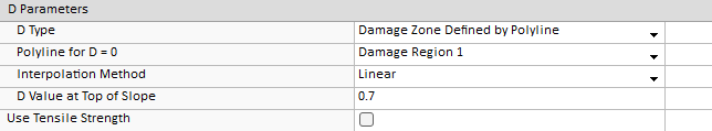
If this option is selected, you can select the polyline that applies to the material using the Polyline for D = 0 dropdown. The polyline that you select will represent the extent of the damaged rock, at which the value of D is zero.
You can also choose either a linear interpolation of the D value between the ground surface and the D polyline or a piecewise interpolation.
The piecewise option allows you to define a table of values which define D as a function of the percentage distance of any point from the ground surface to the polyline, with 0% corresponding to points at the ground surface and 100% corresponding to points at the polyline.
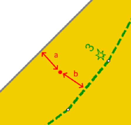
To be clear, the percentage distance is calculated for the point shown in the above figure as a/(a+b)×100%, where a and b are the distances to the closest point on the grounds surface or damage region polyline, respectively.