Set Linear Total Head
The Set Linearly Varied Total Head option allows you to define Total Head boundary conditions which vary linearly along a boundary.
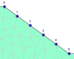
Linearly varying total head (0 to 5) defined on boundary

To use this option:
- Select Set Linearly Varied Total Head from the Mesh menu.
- You will see the Linearly Varied Total Head dialog. Choose the method of varying the Total Head (Vertical Distance or Distance on Boundary), and enter the value of Total Head at Start and Total Head at End. Select OK.
- Use the mouse to select the starting vertex and ending vertex on the desired boundary.
- After the end vertex has been selected, the Linearly Varying Total Head boundary condition will be applied to the boundary, between the start and end vertices you have selected. The value of Total Head at each node of the mesh along the boundary will be displayed.
Calculation of Total Head On Boundary
For the Linearly Varied Total Head option, the Total Head is calculated at each mesh node along the boundary, according to Equation 1.
![]() Eqn.1
Eqn.1
where:
![]() is the Total Head at the start vertex
is the Total Head at the start vertex
![]() is the Total Head at the end vertex
is the Total Head at the end vertex
![]() is the relative distance of the mesh node along the boundary, calculated according to either Equation 2 or Equation 3, depending on the selected method (Vertical Distance or Distance on Boundary).
is the relative distance of the mesh node along the boundary, calculated according to either Equation 2 or Equation 3, depending on the selected method (Vertical Distance or Distance on Boundary).
Vertical Distance Method
For the Vertical Distance method, ![]() is calculated using Equation 2.
is calculated using Equation 2.
![]() Eqn.2
Eqn.2
where:
![]() is the vertical coordinate of the mesh node
is the vertical coordinate of the mesh node
![]() is the vertical coordinate of the start vertex
is the vertical coordinate of the start vertex
![]() is the vertical coordinate of the end vertex
is the vertical coordinate of the end vertex
Distance on Boundary Method
For the Distance on Boundary method, ![]() is calculated using Equation 3.
is calculated using Equation 3.
![]() Eqn.3
Eqn.3
where:
![]() is the distance along the boundary from the start vertex to the mesh node
is the distance along the boundary from the start vertex to the mesh node
![]() is the total distance along the boundary from the start vertex to the end vertex.
is the total distance along the boundary from the start vertex to the end vertex.