Set Boundary Conditions
To analyze a groundwater problem, you will need to define hydraulic boundary conditions for the model. This is done with the Set Boundary Conditions  option.
- Before boundary conditions can be assigned, the finite element mesh must exist. See the Mesh Overview topic for information. If the mesh does not exist, the Set Boundary Conditions option will NOT be enabled.
- When the mesh is generated, default boundary conditions will be in effect on the external boundary: Unknown (P = 0 or Q = 0) on the slope, and Zero Nodal Flow along the left, right and bottom edges of the external boundary.
- In general, the default boundary conditions will need to be customized by the user.
- A specialized option is available for defining Total Head boundary conditions which vary linearly along a boundary. See the Set Linearly Varying Total Head topic for details.
To define groundwater boundary conditions with the Set Boundary Conditions option:
- After the mesh has been generated, select the Set Boundary Conditions option from the toolbar or the Mesh menu. You will see the Set Boundary conditions dialog.
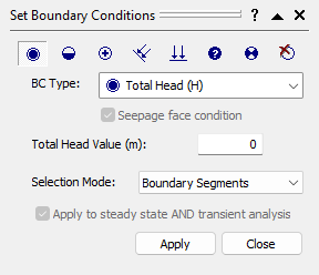
Groundwater Boundary Conditions dialog - In the Set Boundary Conditions dialog, select a Boundary Condition Type that you would like to apply. You can select from the list, or use the icons at the top of the dialog.
- If you are applying Total Head, Nodal Flow Rate, or Infiltration Boundary Conditions, then you must enter a value in the edit box. If you are applying any other boundary condition, then a value is not applicable.
- If you are applying Nodal Flow Rate or Infiltration Boundary Conditions, then you can also specify a Seepage Face condition by selecting the checkbox. See below for more information.
- Boundary conditions can be applied by selecting line segments of the model boundaries, or by selecting nodes of the mesh. Select the desired method from the Pick by list.Infiltration boundary conditions can only be applied to line segments, and not to individual nodes, see below for details.
- Use the mouse to select the boundary segments, or nodes, that you wish to apply the boundary conditions to.
- To apply the boundary conditions, right-click the mouse and select Assign from the popup menu. Or you can select the Apply button in the dialog.
- Repeat steps 2 to 6, until all of the boundary conditions are assigned.
- When you are finished, you can select the Close button in the dialog, or right-click the mouse and select Cancel from the popup menu.
Infiltration Boundary Conditions
Unlike other groundwater boundary conditions, Infiltration boundary conditions can only be applied to line segments of the model, and NOT to individual nodes of the mesh. This is because Infiltration is, by definition, specified over an AREA, and not at POINT locations.
Notice that the units of Infiltration are m / sec (in metric units). This is because Infiltration represents a VOLUME of fluid, entering (or leaving), an AREA of the slope. Therefore, the units are ( m3 / sec ) / (m2) = ( m / sec).
Infiltration can be specified in the VERTICAL direction, or NORMAL to boundaries. In most cases, you will be specifying a VERTICAL Infiltration (e.g. rainfall on the slope). NORMAL infiltration may be required in some cases (for example, if you need to specify Infiltration on a vertical boundary).
Seepage Face Condition
For Infiltration and Nodal Flow Rate boundary conditions you can specify that the boundary is a seepage face. This ensures that the total head calculated at a node does not exceed the elevation head of the node. To enforce the Seepage Face condition, select the checkbox.
Right-Click Shortcut
Boundary conditions can also be assigned, using a right-click shortcut. This is only applicable for boundary segments, and NOT to individual nodes of the mesh.
- After the mesh has been generated, if you right-click the mouse ON any segment of the external boundary or a material boundary, you will see a popup menu, with all of the groundwater boundary condition options.
- Select an option from the popup menu.
- If the option does not require a value (i.e. Zero Pressure, Unknown, or Zero Nodal Flow), then the boundary condition will be assigned immediately to the segment.
- If the option requires a value (i.e. Total Head, Infiltration, or Nodal Flow), then you must enter the value in the prompt line (at the bottom right of the screen), and select Enter. The boundary condition will be applied when you select Enter.