Materials
How can I model an HDPE membrane in Slide2?
There are two methods that people have used to model HDPE liners in Slide2:
The first method is to model an HDPE membrane as a thin material layer with a polyline search focus. See Tutorial 26: Analysis of Embankment using multi-modal optimization (MMO) for more information on doing non-circular searches with a focus entity. Numerous customers of ours use Slide2 for modelling failure along HDPE membranes. As far as the thickness of the HDPE material layer is concerned, there is no limitation but we would suggest a reasonable thickness compared to the overall size of the model (1/100-1/1000 of a typical dimension) just to make the modelling easier. If you did a sensitivity analysis on thickness it would turn out to have little effect on the results at this scale. This method is good for looking at failure along the HDPE-soil interface. In which case you define the strength of the layer as the shear strength of the HDPE-soil interface.
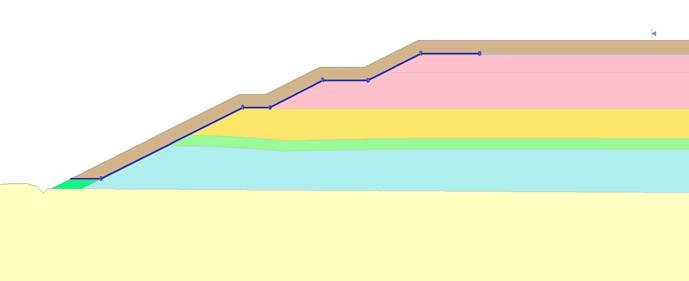
The second method is to use a series of geotextile support elements along the interface (see below image). The tensile strength of the geotextile is basically the rupture strength of the HDPE. This method assumes that failure passes through the HDPE and that the HDPE provides some stability through its tensile strength, similar to a geogrid or geotextile. The only thing we would suggest is that you change the anchorage of the geotextile to both ends. This basically means that the geotextile will always fail in tension and that pullout is not an issue and will not be checked. If the geotextile is buried along the length of the slope, it won’t pull out. This way, you’ll at least know the amount of force (the tensile strength) that the geotextile is putting back into the system.
Can I import material properties from one Slide2 file into another?
Yes, use the Menu option File > Import > Import Properties to read properties from one file to another.
Is there a way to know which portion of a non-circular failure surface is assigned a particular strength when using an anisotropic material?
When using the generalized anisotropic material in Slide2, in order to see which parts of the failure surface are associated with which strength parameters, turn on Slices and Slice Data.
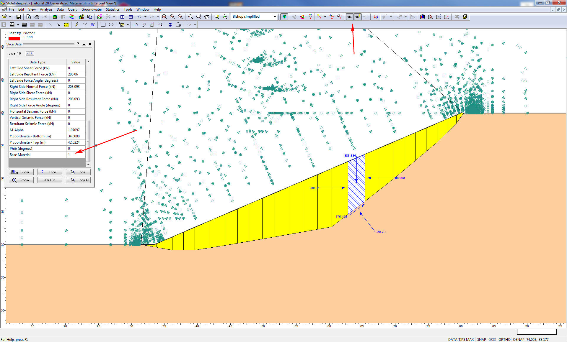
Slice Data in Slide2 Interpret
At the end of the list of slices, data is the material id associated with the base of each slice. You can also look at the strength parameters assigned to the base to double-check which material properties are being used.
How can I perform a statistical analysis in Slide2 using anisotropic materials?
To do this, use Anisotropic Surfaces and assign statistical properties to the parameters.