Anisotropic Surface Overview
The Anisotropic Surface option can only be used in conjunction with the following material strength models:
It allows you to define a surface which represents the average bedding orientation of anisotropic material regions in which the direction of anisotropy changes with location. For example, a folded bedding layer as shown in the figure below.
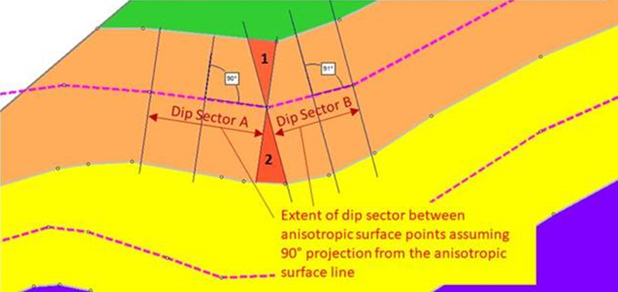
Given a point in space that you want to compute the anisotropic angle, Slide2 first computes the point on the anisotropic surface that’s closest to the point in space that you want to compute the angle. This is not a vertically upward path like a water surface, it’s the closest point. Given the point on the anisotropic surface, Slide2 computes the orientation of the surface at this point and uses this as the anisotropic angle.
In the case where the closest point is a vertex, the program will use the orientation of one of the two line segments which joint to this vertex. The choice is based on which line segment is drawn first when defining the polyline. So if you have large differences in angles between adjoining line segments in the anisotropic polyline, you could get different results depending on which way you draw the polyline. You may ask why we don’t use an average, it’s simply because we wanted to always use a direction defined by the polyline and not an interpolated value.
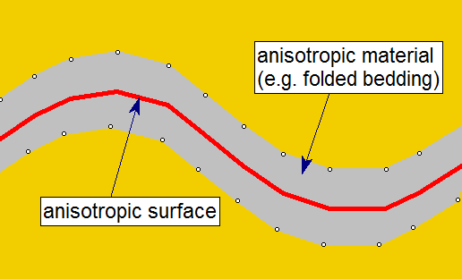
An Anisotropic Surface in conjunction with the above strength options, allows the Slide2 compute engine to determine the local orientation of folded anisotropic regions (for example), in order to apply the correct strength properties at any location.
Add Anisotropic Surface
To add an anisotropic surface to a model use the Add Anisotropic Surface option.
Assign Anisotropic Surface
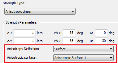
After an anisotropic surface has been created, it must be assigned to a material using the Anisotropic Linear, Snowden Modified Anisotropic Linear or Generalized Anisotropic strength models.
Location of Anisotropic Surface
The exact location of the anisotropic surface is not critical, however, it should be placed such that it best represents the average orientation of the bedding throughout the material.
Typically an Anisotropic Surface is defined near the "middle" of the corresponding anisotropic material region, as shown in the above figure; or it could be coincident with one of the material boundaries (e.g. either the upper or lower boundary of the anisotropic material).
Slide3 Anisotropic Surface
When exporting a 2D section from a Slide3 model with an anisotropic surface, the surface will look different from the 2D surface. It will be gray and labeled "Imported from Slide3." Several unique properties of this surface should be noted:
- 3D properties are contained along the surface. These can be viewed by right-clicking on the surface and selecting "View 3D Details" or by double-clicking on the surface.
- The 3D properties are only used in the analysis if the joint to which the surface is assigned is part of a Generalized Anisotropic function that is using 3D Anisotropy Handling set to "Consider 3D Anisotropy." If "Consider Apparent Dip" is used, the surface is considered as a traditional 2D anisotropic surface.
LEARN MORE
For more detailed instructions on how to add an anisotropic surface, see Tutorial 17: Generalized Anisotropic Material.