Geosynthetic
The Geosynthetic support type can be used to model the various types of slope reinforcement which are used in the form of meshes, grids, strips, etc. There are a wide variety of such support systems, referred to as geo-textiles or geo-fabrics, geo-grids, geo-synthetics etc.
Although the term "Geosynthetic" actually refers to a specific category of reinforcing materials, for the purpose of the following discussion, the term Geosynthetic will be used to refer to all forms of flexible planar reinforcement, which are used in the form of fabrics, meshes, grids, strips, membranes, etc, to reinforce slopes. This includes both synthetic (polymer) and metal (e.g. steel strip) reinforcement.
Strip Coverage
When a Geosynthetic is used to reinforce a slope, the material is placed in strips of a certain width. The Strip Coverage refers to the spacing of these strips, in the Out of Plane direction (i.e. along the slope). If the strips are laid continuously beside each other, with no gaps between adjacent strips, then the Strip Coverage = 100%. If the strips are not laid continuously (i.e. there are spaces between adjacent strips), then the Strip Coverage will be less than 100%. For example, if 4 meter wide strips were laid with a 2 meter spacing between each strip, then the Strip Coverage would equal 67% (i.e. 4 / (4 + 2))
Strip coverage = (a / (a + b) ) x 100
Tensile Strength
The Tensile Strength refers to the Tensile Strength (maximum load capacity, in force units) per meter width of strip (perpendicular to the modelled section). This is also referred to as the Tear Strength, when dealing with geo-fabrics for example.
Force Application
For Geosynthetic support, the default method of Force Application = Passive, since there is normally no significant initial loading or tensioning of the support (although light pre-tensioning is sometimes applied, to optimize the effectiveness of the support). See the Force Application topic for a discussion of the significance of Active and Passive support force application in Slide2.
Force Orientation
Because of the flexible nature of a Geosynthetic type of reinforcement, the orientation of the force which is applied when intersected by the slip surface is NOT always assumed to be parallel to the reinforcement. When the support begins to take on a load, due to displacements within the slope, the direction of the applied support force can be assumed to be:
- Tangent to Slip Surface
- Bisector of Parallel and Tangent (i.e. at an angle which bisects the tangent to slip surface orientation, and the parallel to reinforcement orientation)
- Parallel to Reinforcement
- Horizontal
- User-Defined Angle (i.e. the user may specify an angle, measured from the positive horizontal direction)
Anchorage
When Geosynthetic support is used, the support strips are normally anchored to the slope face, using some type of anchoring system. In addition, the embedded end of the Geosynthetic, may be anchored within the slope. The Anchorage option allows the user to select whether none, both or either end of the Geosynthetic are anchored (i.e. considered fixed and immovable).
The significance of the Anchorage option is as follows:
- If Anchorage = None, then all three failure mechanisms are possible (i.e. tensile, pullout or stripping)
- If Anchorage = Slope Face, then all three failure mechanisms are possible (i.e. tensile, pullout or stripping). The user will also have the option to define the Connection Strength.
- If Anchorage = Embedded End (only), then only tensile failure and stripping are possible (pullout cannot occur).
- If Anchorage = Both Ends, then only tensile failure and stripping are possible (pullout cannot occur). The user will also have the option to define the Connection Strength.
The potential failure modes of a Geosynthetic are very important because they are used to determine the Force Diagram for the Geosynthetic, which in turn determines the magnitude of the applied support force at any point along the Geosynthetic. This is described later in this topic.
Connection Strength
When Anchorage = Slope Face or Anchorage = Both Ends, the user will have the option to define the Connection Strength, meaning the strength with which the Geosynthetic is anchored to the slope face. The options that will appear upon selection of one of these anchorages are described below:
- Connection Strength Input: select Constant to input a constant Connection Strength value. Select Depth-Dependent to input a Connection Strength value that depends on the depth of the Geosynthetic layer. Select Frictional (Linear) to define the connection strength as varying linearly as a function of the normal force, up to the maximum specified strength. Select Frictional (Bilinear) to the define the connection strength as varying linearly as a minimum of two linear functions, up to the maximum specified strength. Select F(depth) to the define the connection strength as varying between the minimum strength and increasing by a rate per unit depth, up to the maximum specific strength.
- If Connection Strength Input = Constant, you will see the following input:
- Connection Strength: constant value considered at slope face end of Geosynthetic.
- If Connection Strength Input = Depth-Dependent, you will see the following inputs:
- Depth-Dependent Connection Strength: the user will be able to input the vertical stress vs connection strength data in tabular format. Higher vertical stress values are associated with higher connection strength values.
- Reference Elevation: the y-coordinate of the reference elevation. The vertical height from this point to the Geosynthetic is used to calculate the vertical stress.
- Unit Weight: the unit weight of material assumed to take up the space between the reference elevation and the geosynthetic. This is used to calculate the vertical stress.Design standards are not applied to this parameter. It is not considered in the same category as the unit weight of the material.
The process of calculating the depth-dependent connection strength is described schematically below.
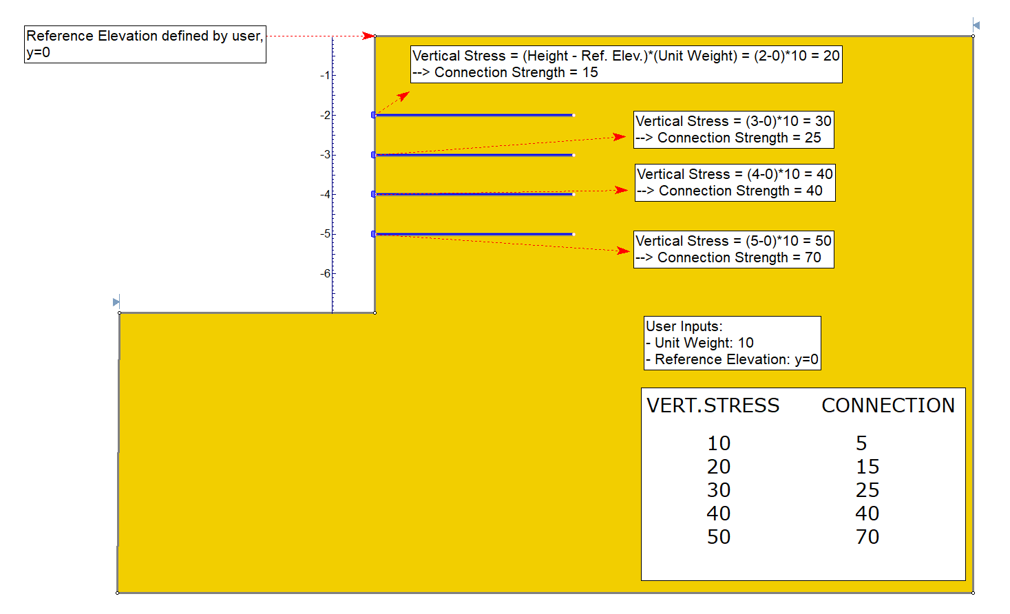
Vertical stress in this context is defined as the unit weight input by the user multiplied by the difference in height. The unit weight has intentionally been made a flexible input such that it can be used to account for things like the weight of concrete block anchorage, or in cases where the slope is at an angle and hence has no slope material vertically upwards.
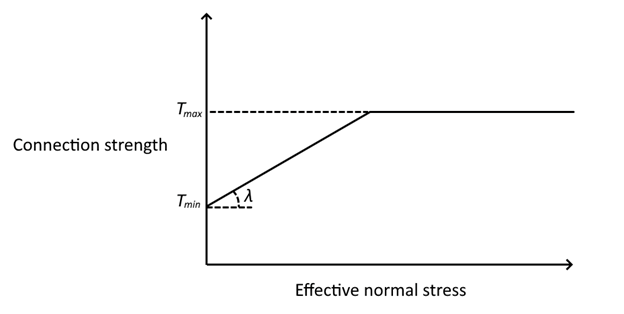
- If Connection Strength Input = Frictional (Linear)
- Minimum Strength: The minimum strength at the slope face end of the geosynthetic
- Maximum Strength: The maximum strength at the slope face end of the geosynthetic
- Friction Angle: The friction angle for the connection strength
- Reference Elevation: the y-coordinate of the reference elevation. The vertical height from this point to the Geosynthetic is used to calculate the vertical stress.
- Unit Weight: the unit weight of material assumed to take up the space between the reference elevation and the geosynthetic. This is used to calculate the vertical stress.
Graphical Representation of Linear Connection Strength Calculation - If Connection Strength Input = Frictional (Bilinear)
- Minimum Strength: The minimum strength at the slope face end of the geosynthetic. This also represents the minimum strength of the first linear function.
- Tangent Strength: The minimum strength of the second linear function.
- Maximum Strength: The maximum strength at the slope face end of the geosynthetic
- Friction Angle 1: The friction angle for the connection strength, related to the minimum (first linear function) strength
- Friction Angle 2: The friction angle for the connection strength, related to the tangent (second linear function) strength
- Reference Elevation: the y-coordinate of the reference elevation. The vertical height from this point to the Geosynthetic is used to calculate the vertical stress.
- Unit Weight: the unit weight of material assumed to take up the space between the reference elevation and the geosynthetic. This is used to calculate the vertical stress.
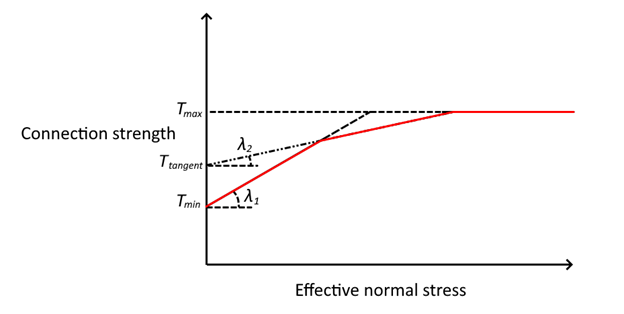
Graphical Representation of Bilinear Connection Strength Calculation - If Connection Strength Input = F(depth)
- Minimum Strength: The minimum strength at the slope face end of the geosynthetic
- Change per unit depth: The rate of change in strength.
- Maximum Strength: The maximum strength at the slope face end of the geosynthetic
- Reference Elevation: the y-coordinate of the reference elevation. The vertical height from this point to the Geosynthetic is used to calculate the vertical stress.
Shear Strength of Interface
The parameters entered here will govern the pullout and/or stripping force, which can be generated by the support.
There are three different methods of defining the shear strength of the interface. The preferred method can be selected with the Input Type dropdown:
- Friction Angle & Adhesion
- Coefficient of Interaction
- Friction Factor
Each input type is described below.
Input Type = Friction Angle & Adhesion
- The definitions of Adhesion and Friction Angle depend on the Strength Model which is used ( Linear or Hyperbolic).
- For analyses involving pore pressure, the normal stress takes into account the pore pressure. Therefore the Adhesion and Friction Angle can be considered effective stress parameters.
- Also see the important note below, regarding the interpretation of the pullout strength parameters for a GeoTextile, and for a Geo-Grid.
Adhesion
- If the Strength Model = Linear, then the Adhesion defines the shear strength of the geosynthetic / soil interface, at zero normal stress, according to the Mohr-Coulomb strength envelope.
- If the Strength Model = Hyperbolic, the Adhesion defines the shear strength of the geosynthetic / soil interface, at high normal stresses. See below for details.
Friction Angle
- If the Strength Model = Linear, then the Friction Angle defines the stress-dependent shear strength of the geosynthetic / soil interface, for normal stress greater than zero. The normal stress (i.e. stress perpendicular to the support) is the result of the weight of soil overburden, and also any other forces due to external or seismic loading.
- If the Strength Model = Hyperbolic, then the Friction Angle defines the initial tangent angle of the hyperbolic shear strength envelope, at zero normal stress. See below for details.
Shear Strength Model
Shear Strength = Linear
If the Shear Strength Model = Linear, this means that the Shear Strength (i.e. Pullout Strength) of the support is determined from the Mohr-Coulomb relationship for the strength of an interface:
| τ = a + σn tan ɸ | Eqn. 1 |
where a = interface adhesion, ɸ = interface friction angle, entered as the Pullout Strength parameters.

For analyses involving pore pressure, the normal stress takes into account the pore pressure. Therefore the Adhesion and Friction Angle can be considered effective stress parameters.
See the additional important note below, regarding the interpretation of the pullout strength parameters, and the normal stress, for a Geosynthetic.
Shear Strength Model = Hyperbolic
When the Shear Strength Model = Hyperbolic, the Shear Strength (i.e. Pullout Strength) of the support, will be determined from the following equation:
 | Eqn. 2 |
This equation was derived from a study of the constitutive behaviour of geosynthetic interfaces [ Esterhuizen, Filz & Duncan (2001) ], and ɸo has been found to characterize the shear strength of soil / geo-synthetic interfaces, and a∞ other types of interfaces. It is important to note the definition of the parameters and in Equation 2. The following figure illustrates a hyperbolic shear strength envelope.

Adhesion a∞ is defined as the shear strength at σn = ∞ . Friction angle ɸo is defined as the friction angle at σn = 0.
If the Strength Model = Hyperbolic, the Adhesion and Friction Angle which you enter as the Pullout Strength parameters must correspond to these definitions.
For analyses involving pore pressure, the normal stress takes into account the pore pressure. Therefore the Adhesion and Friction Angle can be considered effective stress parameters.
See the additional important note below, regarding the interpretation of the pullout strength parameters, and the normal stress, for a GeoTextile.
Input Type = Coefficient of Interaction
In this case the shear strength of the interface is defined as follows:
| τ = Ci (c + σntanɸ ) | Eqn. 3 |
Where Ci is the coefficient of interaction, and c and ɸ are the cohesion and friction angle of the material in which the geosynthetic lies. These are automatically sampled at increments along the geosynthetic. When they are not available, equivalent values are calculated.
Coefficient of Interaction
The coefficient of interaction is used to take some fraction of the shear strength of the surrounding material as the shear strength of the interface. A value of 0 would take no shear strength, whereas a value of 1 would use the full shear strength of the surrounding material.
Input Type = Friction Factor
In this case the shear strength of the interface is defined as follows:
| τ = σnF* | Eqn. 4 |
Where F* is the friction factor.
Friction Factor
The friction factor input by the user is multiplied by the normal stress along the geosynthetic in order to obtain the shear strength of the interface.
You can specify a Constant value for the friction factor or define a function, F(depth), over which its value varies with depth:
- Reference Elevation and Friction factor at top: the value of F* at the specified reference elevation .
- Reference depth and Friction factor at reference depth: specify the value of F* at the specified depth below top of wall.
Material Dependent
The Material Dependent checkbox, allows the user to define the pullout strength or stripping of the Geosynthetic, according to the material(s) which the support passes through. In order to use this option:
- Select the Material Dependent checkbox, and select the Define button.
- You will see the Pullout Strength dialog. In this dialog, select the Add Material button, for each material that you wish to define the pullout strength for.
- For each material, use the mouse to select a Material Name, and enter the parameters for the material. The Material Names correspond to the materials you have defined in the Define Material Properties dialog.
- Any material which you have NOT included in the Pullout Strength dialog, will use the Pullout Strength parameters which you have entered in the Define Support Properties dialog.
- When you are finished customizing the Pullout Strength parameters for all the required materials, select OK in the Pullout Strength dialog.
Interpretation of Geosynthetic Shear Strength Parameters
In order to correctly interpret the definition of the parameters, used to define the Pullout Strength of a GeoTextile in Slide2, it is important to understand the following:
- The parameters define the shear strength of the Geosynthetic / Soil interface.
- However, a Geosynthetic embedded in soil has TWO interfaces with the soil. When pullout occurs, the shear strength of BOTH interfaces must be accounted for by the pullout force.
For example, consider a unit width of Geosynthetic, with Length = L and Pullout Force = P.

The relationship between the pullout FORCE (P) and the SHEAR STRENGTH (τ) is therefore:
P = 2τL (or τ = P / 2L)
When the pullout and stripping forces are calculated for a Geosynthetic in Slide2, a factor of 2 is included in the force calculation, in order to account for the shear strength of BOTH sides of the Geosynthetic (see below for equations). NOTE that this applies to both Linear or Hyperbolic shear strength models in Slide2.
This interpretation of Geosynthetic pullout strength is applicable to geo-textiles, geo-fabrics, metal strips, etc., which have a 100% contact area with the soil (i.e. there are no "holes" in the material, and the Geosynthetic / Soil interface is continuous).
When dealing with Geo-Grids and similar products, which have a significant area of soil-soil contact, through the holes in the Geo-Grid, this relationship is a simplification of the true failure mode.
- For Geo-Grids shear resistance is not uniform along the length of the material (i.e. Adhesion and Friction Angle are different for the Geosynthetic / Soil interface, and the soil / soil interface).
- Furthermore, the pullout capacity is mainly developed as the bearing earth pressure against the transverse elements of the grid [ Forsman & Slunga (1994) ].
Normal Stress
In general, the normal stress, which is used in the shear strength equations (Eqn.1 or Eqn.2) will vary along the length of a Geosynthetic. The normal stress is determined as follows:
- Each Geosynthetic support element is first subdivided into 50 equal segments.
- For each subdivision along the geosynthetic, the vertical stress is determined from the overburden stress, as well as any vertical component of external loading which acts on the slope above the geosynthetic.
- In most cases, geosynthetics are placed horizontally, therefore the normal stress σn is equal to the vertical stress σv. In cases where geosynthetics are not placed horizontally, hydrostatic stress is assumed, so again, the normal stress is equal to the vertical stress.
- For analyses involving pore pressure, the normal stress takes into account the pore pressure and is therefore the effective normal stress.
- The normal stress is then used to compute the frictional pullout force which can be contributed by each subdivision along the length of the GeoTextile.
Consider Sliding Along Interface
In addition to considering the failure of a geosynthetic intersected by a slip surface, you can also elect to consider the additional failure mode of a slip surface sliding along the geosynthetic interface (via Pullout and Stripping tab > Consider sliding along interface).
When this option is toggled, the computations will also consider the geosynthetic as a weak layer, which clips the slip surfaces that intersect it.
- The strength of the weak layer will be calculated based on the parameters you define in Shear Strength of Interface (i.e. Adhesion & Friction Angle, Coefficient of Interaction, or Friction Factor).
- Where necessary, effective values of the adhesion (i.e. cohesion) and friction angle will be estimated if they are not explicitly defined in the geosynthetic properties and/or material layer immediately above the geosynthetic, whichever is required.
Further Reading
Further information regarding Geosynthetic uses and properties, can be found in Jewell (1996) . In particular, Chapter 4 of this reference provides insight into the behaviour of Geotextiles and GeoGrids in reinforced slopes, and the significance of the "bond coefficients", which are commonly used to describe the shear strength of the Geosynthetic / Soil interface.
Implementation of Geosynthetic Support in Slide2
The Geosynthetic properties which are entered in the Define Support Properties dialog, are used to determine a Force Diagram for a Geosynthetic, as described below.
Consider a Geosynthetic which intersects a slip surface as shown below.

Li = length of geotextile within sliding mass
Lo = length of geotextile embedded beyond slip surface
Geosynthetic parameters
A = Strip Coverage (%)
T = Tensile Strength (force / width)
C = Connection Strength (force / width)
Where the slip surface intersects the support, three failure modes are possible depending on the setting of the Anchorage option.
- Tensile (always possible, for all Anchorage settings)
- Pullout (only if Anchorage = None or Slope Face)
- Stripping (always possible, for all Anchorage settings)
Pullout
For a geosynthetic, pullout can only occur if the embedded end is NOT anchored (i.e. Anchorage = Slope Face or Anchorage = None). The maximum pullout force which can be mobilized, PER UNIT WIDTH OF SLOPE, is given by:
| F1 = 2LoAτ / 100 | Eqn. 5 |
where the shear strength τ is calculated as described above according to the input Type selected by the user.
Material Dependent Shear Strength
If the Geosynthetic Pullout Strength is specified as Material Dependent, then the Pullout Force is determined by integrating along the length of the Geosynthetic, to determine the force contributed by each segment of the Geosynthetic which passes through different materials. In this case, Equation 5 will use the appropriate parameter for each material.
Tensile Failure
Tensile Failure of a geosynthetic is ALWAYS a possible failure mode, regardless of the setting of the Anchorage option. At any point along the geosynthetic, the maximum tensile load, PER UNIT WIDTH OF SLOPE, which can be mobilized by the geosynthetic, is simply given by:
| F2 = TA/100 | Eqn. 6 |
Stripping
Stripping is the term used in Slide2, when support failure occurs by the sliding mass "stripping" off of the support (i.e. the support remains embedded in the slope).
NOTE that for geosynthetic support in Slide2, stripping is possible for all Anchorage selections. Even if the geosynthetics are anchored to the Slope Face, stripping could occur if the connection strength is less than the tensile strength. The force required for the sliding mass to "strip" off of the support, is given by:
 |
Eqn. 7 |
where the shear strength τ is calculated as described above according to the Input Type selected by the user.
Force Diagram
At any point along the length of a geosynthetic, the magnitude of the force which will be applied to a slip surface which intersects the Geosynthetic, is given by the minimum of the Tensile, Pullout (if applicable), and Stripping forces. This depends on the setting of the Anchorage option, as follows:
- Anchorage = None → Applied Force = min (F1, F2, F3)
- Anchorage = Slope Face → Applied Force = min (F1, F2, F3)
- Anchorage = Embedded End → Applied Force = min (F2, F3)
- Anchorage = Both Ends → Applied Force = min (F2, F3)
In most cases, a Geosynthetic will be anchored to the slope face, but not anchored within the slope (i.e. Anchorage = Slope Face). In this case, the Force Diagram for a Geosynthetic will resemble the following figure, in which all three failure modes are considered.
Force diagrams are not shown for the mode of sliding along the top of the geosynthetic interface.
References
- Esterhuizen, J., Filz, G.M. and Duncan, J.M., Constitutive Behaviour of Geosynthetic Interfaces, Journal of GeoTechnical and Geoenvironmental Engineering, October 2001, pp 834-840.
- Forsman, J. and Slunga, E., The Interface Friction and Anchor Capacity of Synthetic Georeinforcements, Fifth International Conference on Geotextiles, Geomembranes and Related Products, Singapore, September 1994.
- Jewell, R.A., Soil Reinforcement With Geotextiles, Special Publication 123, Construction Industry Research and Information Association, London, 1996.