Pile / Micro Pile
The Pile / Micro Pile support type can be used to model a micro pile or pile type of support system. Due to the nature of pile support, this type of support behaves differently from other types of support in Slide2, since resistance to movement is assumed to be provided by loading transverse to the support direction, rather than parallel to the support direction. Note:
- Like all other support types in Slide2, it is necessary for a slip surface to intersect a pile, in order for the support to have an effect on the safety factor of the slip surface.
- Three failure modes are considered for this support: shear, Ito & Matsui, and EFW. In all cases, the failure occurs transversely through the pile.
- Tension or pullout are NOT considered as failure modes for a pile in Slide2, regardless of the pile orientation. Only transverse shear through the pile is considered.
Shear Failure
The Pile Shear Strength, is the shear FORCE necessary to cause shear failure THROUGH the pile, as illustrated below.
Out of Plane Spacing
The spacing between soil nails in the out-of-plane direction (i.e. along the slope), measured from center to center.
Force Application
By default, if Support Type = Micro Pile, the method of Force Application = Passive. See the Force Application topic for a discussion of the significance of Active and Passive support force application in Slide2.
Force Orientation
When a slip surface intersects a Micro Pile, the default orientation of the applied force (i.e. the Pile Shear Strength) is TANGENTIAL to the slip surface. This is illustrated below. This force orientation is consistent with the assumed failure mode of a Micro Pile. You can also choose Perpendicular to pile as the force orientation if you want the applied force to be exactly perpendicular to the pile regardless of the slip surface orientation.
Implementation of Pile Support in Slide2: Failure Mode = Shear
As discussed above, a pile will apply a constant force to a slip surface, regardless of where it is intersected by a slip surface. The applied load, PER UNIT WIDTH OF SLOPE, is simply equal to the Pile Shear Strength divided by the Out of Plane Spacing. i.e.
F = P / S
where:
P = Pile Shear Strength (force units)
S = Out of Plane Spacing
The Force Diagram for a Pile support type, is therefore a horizontal line, representing a constant value of applied force, regardless of where a slip surface intersects the pile.
Ito & Matsui
The Ito & Matsui mode pertains to piles that are surrounded by plastically deforming ground. This is modeled after Ito & Matsui (1975). The lateral force acting on a pile per unit thickness of soil layer is described as shown (details can be found in the paper):
The force applied is therefore obtained by the integration of this equation from the top of the pile to the intersection with the slip surface.
Pile Diameter
The diameter of the pile.
Location of Force
The force can be specified at the slip surface intersection point as with other support options in Slide2. It can also be specified as the centroid of the pressure diagram obtained from the equation above.
Force Orientation
The same options available in the Shear failure option are available here.
Implementation of Pile Support in Slide2: Failure Mode = Ito & Matsui
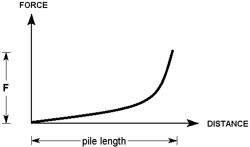
The Ito & Matsui pile applies a force to the slip surface based on the method outlined by Ito & Matsui (1975), PER UNIT WIDTH OF SLOPE. It is dependent on the soil cohesion and friction angle (or equivalent values), the diameter of the pile, and the vertical stress. As such for a single material, the force would increase with depth as shown. However, if the pile intersects multiple materials it will vary since it is dependent on the material properties.

Equivalent Fluid Weight (EFW)
Pile designs are often provided to the structural engineer as an equivalent fluid weight. This option allows the user to input this value directly. This results in a trapezoidal distribution of the total force along the pile length, with the default resultant force applied at the centroid.
This support option can also be used to model the analysis of a failure beneath a retaining wall. The wall can be modelled as a pile with a triangular EFW. Slip surfaces that pass beneath the pile would not include the EFW.
Constant Pressure
The value of the pressure at the top of the pile. c in the figure.
Fluid Unit Weight
The equivalent fluid unit weight of the pile, or the slope in the pressure diagram figure.
Location of Force
The force can be specified at the slip surface intersection point as with other support options in Slide2. It can also be specified as the centroid of the trapezoidal pressure diagram shown in the figure.
Force Orientation
The same options available in the Shear and Ito & Matsui failure options are available here, with the additional “Horizontal” option.
Implementation of Pile Support in Slide2: Failure Mode = EFW
The applied force, PER UNIT WIDTH OF SLOPE, is calculated as follows
F = P / S
where:
P = Area of trapezoid shown = (Constant Pressure)*(distance between top of pile and slip surface intersection point) + (Fluid Unit Weight)*(distance between top of pile and slip surface intersection point)2/2.0
= c*H + efw*H2/2.0
S = Out of Plane Spacing.
If the value provided for constant pressure and fluid unit weight is for a group of piles, the components are assumed to act over 1.0 units and thus the Out-of-Plane Spacing value should remain as 1.0. If for a single pile, ensure the spacing is set to the correct spacing of bolts.
Because of this additional consideration of out-of-plane spacing, the pressure diagram is conceptually defined in units of force per depth of soil. The equation can be represented as such
P = c*H * 1.0 + (efw * 1.0)*H2/2.0
With final units of force / length
As such the force increases with depth, as shown.