Damage Region Overview
A damage region defines the zone in which the parameter D disturbance factor for Generalized Hoek-Brown materials varies from 0 (undisturbed) to 1 (very disturbed) which subsequently affects the strength of the material. This degree of disturbance is based on the reduced material properties due to blast damage and/or stress relaxation and can be spatially defined via damage regions polylines.
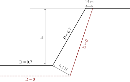
For example, the disturbance factor varies from 0.7 to 0 across the slope region up to 0.3 times the height at base of the slope.
Add Damage Region
To define a damage region, use the Add Damage Region (D = 0) option. Select the points within the model that will define the damage region polyline where D = 0 and press Enter to finish. Any number of damage regions can be defined.
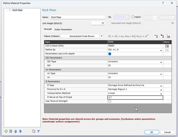
Once defined, any Generalized Hoek-Brown material can have its D parameter assigned to any number of damage regions. This is assigned by first setting the D Type to Damage Zone Defined by Polyline and selecting the associated Damage Region in the Polyline for D = 0 field.
The following interpolation values are supported:
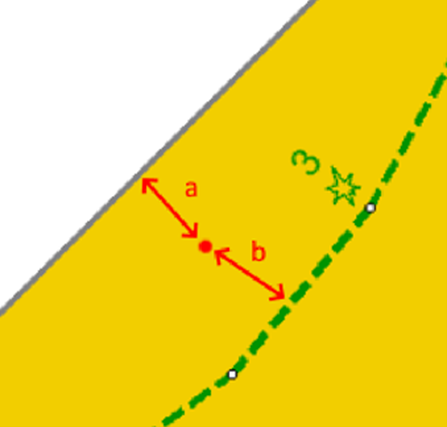
- Linear – If selected, the interpolation of the D parameter is based on the vertical distance between the top of the damage region external boundary and the defined damage region polyline where D = 0
- Piecewise – If selected, the option allows you to define a table of values defining D as a percentage distance from an arbitrary point from the ground surface to the polyline where 0% corresponds to the points at ground surface and 100% corresponds to the polyline points.
The D value at the top of the slope is the value along the topmost external boundary defined within the damage region. The linear interpolation occurs between this value and the value at 0 at the end of the damage region.
In the Interpreter, the D parameters that are assigned to each slice during computation can be viewed via Query Slice Data > Show Values Along Surface and selecting Slice Data: Generalized Hoek-Brown D.
See the Damage Region Tutorial for more details.