Helical Anchor
Helical anchors, also known as screw anchors or soil screws, are deep foundation supports composed of steel helical plates welded to a shaft, providing additional resistance for slopes or retaining walls.
Tensile Capacity
The Tensile Capacity entered for a Helical Anchor, represents the maximum tensile capacity of the steel shaft, independent of the helix capacity. Units are Force.
Head Assembly Capacity
The Head Assembly Capacity is the maximum load which can be sustained by the head assembly which connects the anchor to the slope. Units are Force. Head assemblies in other Slide2 support types are typically called plates. To avoid confusion with the helical plates, the term head assembly will be used instead.
Shear Capacity
The Shear Capacity is optional, and allows you to account for shear failure through the anchor cross-section (i.e. the force required to shear the anchor perpendicular to its axis). Units are Force. See below for implementation details.
Compression Capacity
The Compression Capacity is optional and allows you to account for failure of the shaft in compression. Units are Force. See below for implementation details.
Out of Plane Spacing
The spacing between soil nails in the out-of-plane direction (i.e. along the slope), measured from center to center.
Force Application
For the Helical Anchor support, the default method of Force Application = Active. See the Force Application topic for a discussion of the significance of Active and Passive support force application in Slide2.
Force Orientation
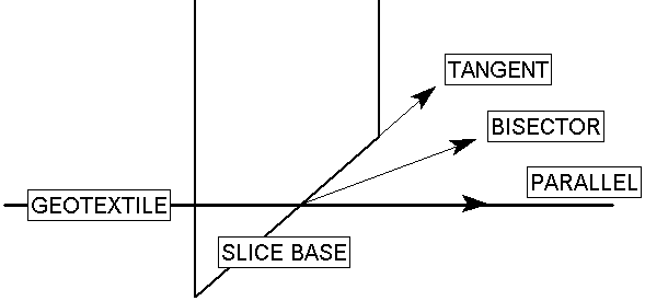
When the support begins to take on load, due to displacements within the slope, the direction of the applied support force can be assumed to be:
- Tangent to Slip Surface
- Bisector of Parallel and Tangent (i.e. at an angle which bisects the tangent to slip surface orientation, and the parallel to reinforcement orientation)
- Parallel to Reinforcement
- Horizontal
- User-Defined Angle (i.e. the user may specify an angle, measured from the positive horizontal direction)
Anchor Dimensions and Parameters
Most of the inputs are similar to the Grouted Tieback support type but include parameters unique to helical anchors. For info on the shared parameters, see the Grouted Tieback support topic. Unique to the helical anchor support type are the shaft and plate dimensions and parameters which can be specified.
Shaft type – Can be specified as round or square.
Shaft width/diameter – The width or diameter of the shaft represents the measurement of a square or round shaft respectively.
Number of helices – Specifies the number of helices along the anchor. A minimum of one anchor is required.
Average helix diameter – The average helix diameter
Helix Spacing – Spacing between two helices. Assumes all helices are spaced equally. Note this input only appears when the input for number of helices is greater than or equal to 2.
Due to the shaft going through the helix, the effective area of the plate is reduced. As such, the equivalent projected area (EPA) of the helix can be determined as:
Helix Area – Shaft Area
In the case of average helix diameter, the EPA is also the average EPA.
Note:
- It is assumed that the last plate is located at the end of the anchor and subsequent plates are generated from the first plate based on the number of plates and spacing.
- In the case of unfeasible inputs (e.g. if user inputs Number of Helices = 2, Helix Spacing = 2 m, and defines a support that is 1 m long), then the Number of Helices input takes precedence. Helix Spacing is automatically adjusted on the visual display of the support and during computation as follows:
Helix Spacing = support length / (Number of Helices – 1)
Recommended Dimensions
Many design guides provide appropriate recommendations regarding the embedment depth of the anchor and spacing of the plates, as well as specifications for anchor products. In the event the dimensions are not provided, the following design recommendations have been provided to reduce any unexpected behaviour of the anchor:
- Spacing should be 5-12 times the average helix diameter
- The helix diameter should be significantly larger than the shaft such that the shaft should be contained within the circular helix.
Pullout Strength
For a Helical Anchor, the Pullout Strength is simply expressed as a Force per unit Length. NOTE that the LENGTH units in this case, refer to the LENGTH ALONG THE ANCHOR. The maximum pullout force is therefore simply the length of the helical anchor, multiplied by the soil pullout strength.
Definition of Frictional Area for Helical Anchors
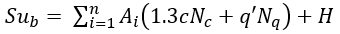
- The shear strength along the shaft length is calculated from the shear strength of the surrounding soil. The strength is sampled at increments along the support.
- The effective stress which is calculated is assumed to be uniformly distributed around the shaft and soil surface and is also assumed to be equal to the vertical stress. The vertical stress is determined from the weight of soil overburden and also the vertical component of any external loading sampled at intervals along the support
- The cylindrical soil failure surface area is then multiplied by the shear strength along the effective length, in order to obtain the maximum shear force which can be generated by pullout (or stripping) of the helical anchor (see below for equations).
Implementation of Helical Anchor Support in Slide2
The Helical Anchor properties which are entered in the Define Support Properties dialog, are used to determine a Force Diagram for a Helical Anchor, as described below.
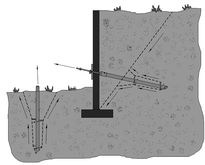
Consider a Helical Anchor, which intersects a slip surface, as shown below.
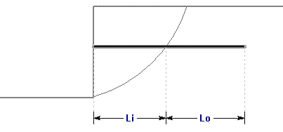
Li = length of helical anchor within sliding mass
Lo = length of helical anchor embedded beyond slip surface
Helical Anchor Parameters:
S = Out of Plane Spacing (distance)
T = Tensile Capacity (force)

c = Cohesion (force/area)
H = Head Assembly Capacity (force)
For a Helical Anchor, at any point along the length of the anchor, there are 3 possible failure modes which are considered:
- Pullout (force required to pull the length Lo of the anchor out of the slope)
- Tensile Failure (maximum axial capacity of the shaft)
- Stripping (slope failure occurs, but anchor remains embedded in slope)
Helical Anchor Pullout
The helical anchor capacity calculations are based of Terzaghi’s and Meyerhof’s theory of bearing capacity and are used for both compression and pullout capacity (Perko, 2009). The pullout strength of a helical anchor is derived from comparing two failure scenarios: shallow failure and deep failure.
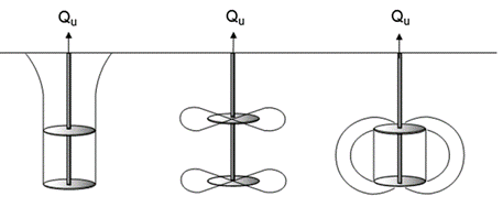
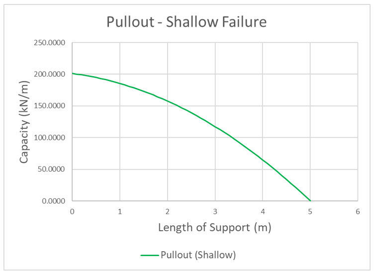
Shallow failure
Shallow failure occurs when the soil failure surface of the mobilized soil within the anchor extends to the surface. As the name suggests, shallow failure is most likely to occur at shallow embedment depths. The failure surface is assumed to form a cylindrical shape between the shallowest and deepest anchors to the surface.
Shear strength is assumed to develop along the surface area of the cylinder. At any point along the support, the ultimate pullout capacity for shallow failure can be determined using the following equation:
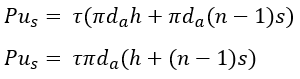 | Eqn. 1 |
where h is the distance from the slip surface to the shallowest helix along the anchor, also known as embedment depth, is average helix diameter, n is the total number of helices within the soil, and s is the spacing between helices.
Deep failure
At a critical embedment depth, the failure mode transitions from shallow failure to deep failure. Deep failure occurs when the mobilized cylinder of soil fails, but no breakout occurs at the surface. Deep failure can be split into two main failure types: global deep failure and local deep failure, which are also known as cylindrical shear and individual bearing, respectively.
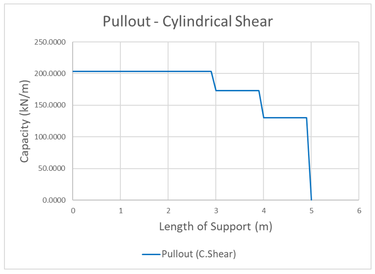
Cylindrical Shear
In cylindrical shear, the mobilized soil between the plates forms a cylindrical volume of soil, similar to shallow failure (Perko, 2009). However, the bearing capacity of the shallowest plate is considered rather than a mobilized cylinder of soil that extends to the surface. At any point along the support, the ultimate pullout capacity in cylindrical shear can be determined using the following equation:
 | Eqn. 2 |
where is the EPA of the shallowest helix from the slip surface, c is the cohesion of the soil, and q’ is the effective stress at helix , The factors and are the bearing capacity factors for cohesion and overburden, respectively (Perko, 2009). and can be determined using the following equations:
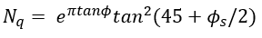 | Eqn. 3 |
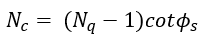 | Eqn. 4 |
where is the friction angle of the soil (Perko, 2009). As approaches 0, Nc converges to approximately 5.14. Therefore, the minimum value of Nc is set to 5.14. It is important to note that at any point within the slope there exists only one plate, no cylindrical soil mass will be mobilized and only the bearing capacity of the plate is considered.
Individual Bearing
At a critical helix spacing, the deep failure mode transitions from cylindrical shear to individual bearing. In individual bearing, all plates fail within an area of localized soil, independent of one another (Perko, 2009). The pullout capacity can then be described as the sum of the bearing capacities for each plate. At any point along the support, the ultimate pullout capacity for individual bearing can be determined using the following equations:
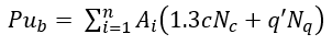 | Eqn. 5 |
where is the equivalent projected area of helix i (Perko, 2009).
More information regarding the force diagrams can be found in the Force Diagram section.
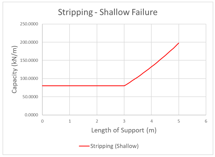
Helical Anchor Stripping
The stripping capacity of the helical anchor utilizes the same equations for pullout. Stripping is determined in a similar fashion with the addition of the head assembly capacity H. The equations for shallow failure, cylindrical shear, and individual bearing, respectively are as follows:
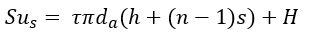 | Eqn. 6 |
 | Eqn. 7 |
 | Eqn. 8 |
Typical force diagrams for the failure types can be found in the following figures.
More information regarding the force diagrams can be found in the Force Diagram section.
Consideration of Shallow Failure
While individual bearing and cylindrical shear are commonly considered in current design guides, shallow failure is typically prevented by providing a minimum embedment depth, despite its importance in determining an accurate force diagram. Shallow failure should be included due to two main reasons.
Firstly, shallow failure is incredibly important to consider with slip surfaces. Many design guides omit the provided calculation method since providing a minimum embedment depth for installers prevents shallow failure from occurring. However, as the slip surface moves deeper into the slope along an anchor, a plate may be extremely close to that surface, despite the sufficient embedment depth from the actual surface. As such, shallow failure needs to be considered at all points along the anchor.
Secondly, the current methods of individual bearing and cylindrical shear fail to account for non-vertical situations. As an extreme example, consider the following scenario: a single horizontal helical anchor with three plates is embedded in a flat wall. Because both individual bearing and cylindrical shear consider the bearing capacity through effective stress, an anchor installed 2 m from the horizontal surface would have less capacity then a anchor installed 10 m from the surface even if both are embedded the same horizontal distance. If an anchor is embedded a significant distance from the vertical surface but the shallowest plate is very close to the horizontal surface, the bearing capacity of that helix will be relatively high but is unrepresentative of the more likely failure shallow failure. With the addition of shallow failure, the analysis provides a more accurate depiction of how an anchor would fail.
Overall Capacity
Due to the variation of critical embedment depth and critical spacing across literature, the pullout strength of the anchor is given by the minimum pullout capacity of the three failure types.
In total, three modes of failure are considered. The maximum force which can be mobilized by each failure mode, PER UNIT WIDTH OF SLOPE, is given by the following equations:
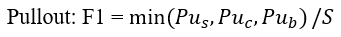 | Eqn. 9 |
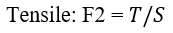 | Eqn. 10 |
 | Eqn. 11 |
where S is the out of plane spacing.
At any point along the length of the tieback, the force which is applied to the slip surface by the tieback, is given by the MINIMUM of these three forces.
Applied Force = min(F1, F2, F3) Eqn.14
NOTE:
- In order for stripping to occur, the Head Assembly Capacity must be exceeded. The Head Assembly Capacity is included in the stripping force equation, and added to the shear capacity along the length Li.
- Other potential failure modes for helical anchors exist which include, but are not limited to, buckling, plate weld failure, and lateral failure. However, because the majority of these failure modes are related to the structural integrity of the support itself, the anchor is assumed to be sufficiently designed for the purposes of the analysis.
Shear capacity and compression capacity can also be implemented, similar to the Grouted Tieback support type. For a description of these additional capacity considerations, see the Grouted Tieback support topic.
Force Diagrams
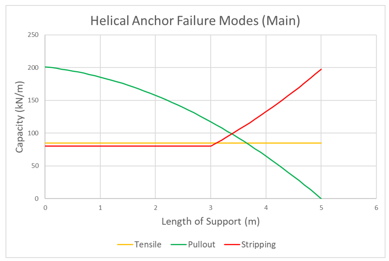
The force diagram for the helical anchor will resemble the following, in which all three failure modes are considered.
The following figure displays all three main failure modes. Note that the minimum capacity along the length of the support creates the force envelope shown in the previous figure.
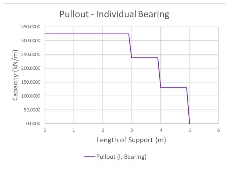
Analysis of Force Diagrams – Pullout
The following figure displays the typical force diagrams for all three pullout failure types.
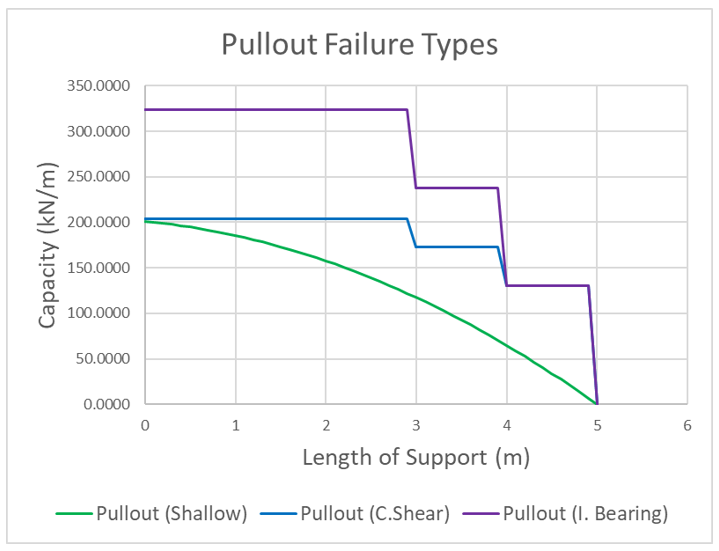
As the slip surface progresses along the anchor, the anchor force and overall pullout capacity decreases. In this scenario, shallow failure governs. This specific anchor has three helices and each step shown represents the passing of a helix. While individual bearing capacity is significantly greater than cylindrical shear at the beginning of the anchor, the capacities of both are equal after the second-last helix is passed. This is due to the fact no cylindrical soil is mobilized for cylindrical shear after the second-last helix. In pullout, this state of equal capacity before the last helix holds true for any anchor and is assumed to fail in individual bearing if found to be the minimum. Once the final helix is surpassed, no capacity exists.
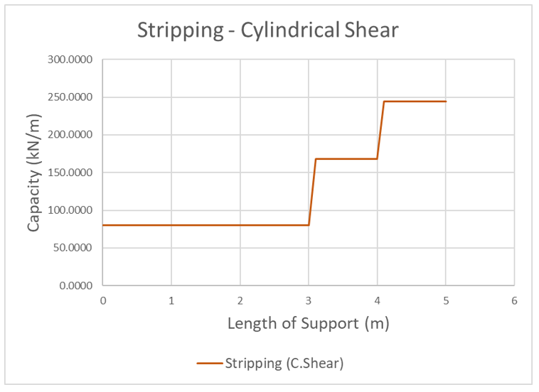
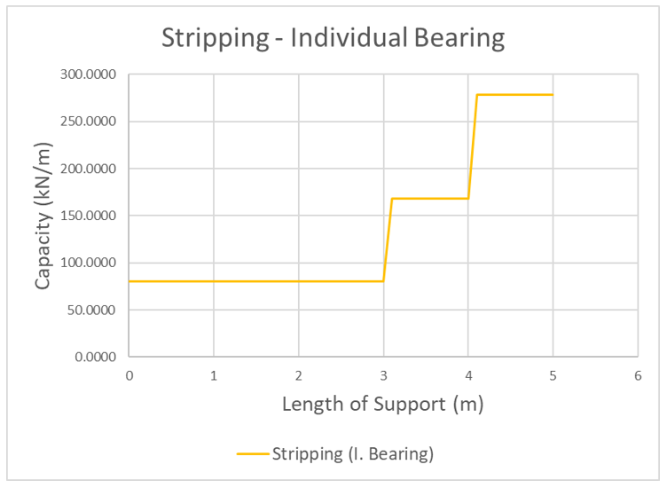
Analysis of Force Diagrams – Stripping
Because stripping of the anchor acts as reverse pullout, the trends in the force diagram are also expected to be reversed. The following figure displays the typical force diagrams for all three stripping failure types.
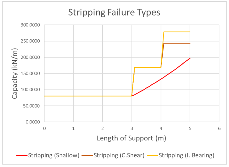
As the slip surface progresses along the anchor, the anchor force and overall stripping capacity increases. Initially, since no plates exist within the sliding mass, all capacities are equal to the head assembly capacity and assumed to fail in shallow failure. In this scenario, shallow failure governs. This specific anchor has three helices and each step shown represents the passing of a helix. While individual bearing capacity is significantly greater than cylindrical shear at the end of the anchor, the capacities of both are equal before the second helix is passed. This is due to the fact no cylindrical soil is mobilized for cylindrical shear before the second helix. In stripping, this state of equal capacity before the second helix holds true for any multi-helix anchor and is assumed to fail in individual bearing if found to be the minimum.
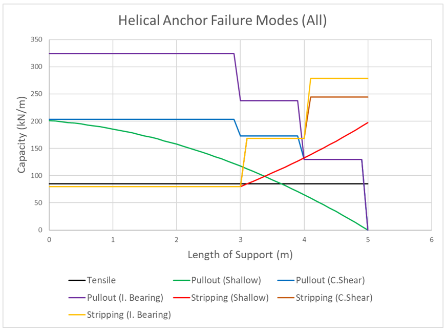
Depending on the parameters of the helical anchor and soil, the trends between the failure types and governing failure type will vary. For example, if the spacing ratio is significant, individual bearing is expected to govern rather than shallow failure in both pullout and stripping. The following figure considers all 7 failure modes (tensile and three failure types for pullout and stripping each).
References
Kwon, O., Lee, J., Kim, G., Kim, I., & Lee, J. (2019). Investigation of Pullout Capacity for Helical Anchors Subjected to Inclined Loading Conditions Using Coupled Eulerian-Lagrangian Analyses. Computers and Geotechnics, 66-75.
Perko, H. A. (2009). Helical Piles: A Practical Guide to Installation. Hoboken: John Wiley & Sons Inc. .