User-Defined Support
It is important to realize that all of the pre-defined support types in Slide3, i.e.
- End Anchored
- Geosynthetic
- Grouted Tieback
- Micro Pile
- Soil Nail
are simply used to generate a Force Diagram for the support (i.e. a plot of FORCE versus DISTANCE along the support). The way in which this graph is generated differs for each type of support, and depends on the support parameters which are entered. However, as far as the Slide3 COMPUTE engine is concerned, the properties of an anchor are entirely determined by the Force Diagram (as well as the method of Force Application, and the Force Orientation, which are independently specified).
The Slide3 implementation of the user-defined support feature is essentially the same as the Slide2 implementation. Please see Slide2 Documentation | User-Defined Support for further details and other examples.
EXAMPLE
As an example, we will replicate the soil nails from the Slide3 Reinforced Slope tutorial. The Force Diagram (FD) and support forces are shown below for a set of 12m supports:
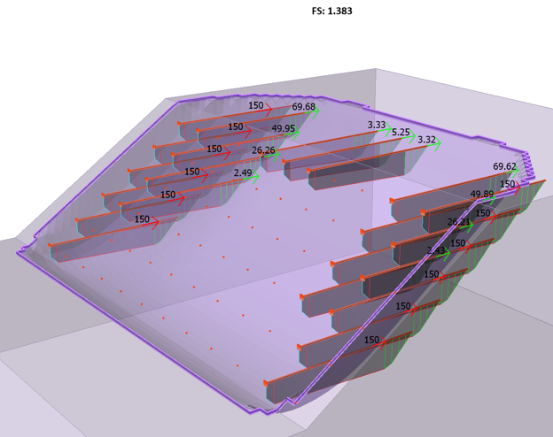
Similar to the tutorial, the FD shows the governing capacity is either tensile or pullout. Stripping capacity is present but is not considered to be governing. Regardless, we should define all 3 capacities.
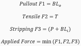
As defined in the Soil Nail documentation, the capacities are calculated as the following:
We can then begin to define capacities in a new support type, keeping the same general settings as the existing soil nail. Ensure each capacity that we want to utilize has “Consider Capacity Type” on.
Tensile capacity is defined as the following:
- Type: Constant
- Value: 150kN
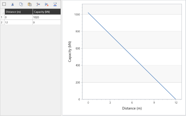
Pullout capacity is calculated as the bond strength multiplied by the embedded bond length. This means if the surface intersects 2m along the support, there is 10m of embedded bond length. This linear increase means we can simply define the capacity at the start and end points of the support, which are B * L and 0kN respectively.
As such, given a bond strength of 85kN/m the pullout capacity defined over the length is simply:
- Type: User-Defined
- In the User-Defined Edit Option:
- Distance: 0m, Capacity: 12m * 85kN/m = 1020kN
- Distance: 12m, Capacity: 0kN
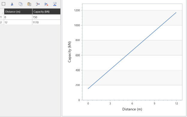
Stripping capacity could be considered the “reverse” of pullout capacity. A surface intersecting at 2m along the support means there is 2m of the support being “stripped” from the moving soil mass. However, stripping capacity includes the plate capacity. Given a plate capacity of 150kN, we define stripping capacity as the following:
- Type: User-Defined
- In the User-Defined Edit Option:
- Distance: 0m, Capacity: 150kN
- Distance: 12m, Capacity: 12m * 85kN/m + 150kN = 1170kN
When computing, we find that the user-defined FD, support forces, and FS are the same compared to the actual soil nail support forces:
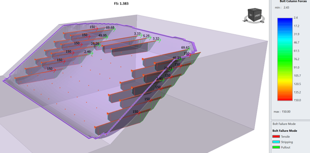
While this is a simpler example, we are nevertheless capable of replicating the soil nail using the user-defined support type.