Overview of Support Implementation
Before we describe the implementation of the different types of support in Slide3, we will summarize the following general rules, which apply to all support types used in Slide3.
Intersection with Slip Surface
First of all, in order for the support to have an effect on a given slip surface, the support must intersect the slip surface. If the support does NOT intersect a slip surface, then NO support force will be applied to the slip surface, and the support will have no effect on the safety factor of that slip surface.
Support does NOT intersect slip surface – NO effect on safety factor
Support intersects slip surface – support force will be applied
Location of Applied Support Force
When support intersects a slip surface, a force is applied at the point of intersection of the slip surface with the support.
- For bolts (e.g. tiebacks, soil nails) a line load is applied to the base of a single column.
- For geotextiles, the applied load may be distributed over adjacent columns.
In either case, the applied support force is a line load with units of FORCE.
Orientation of Applied Support Force
The orientation of the applied support force will depend on the type of support which is used.
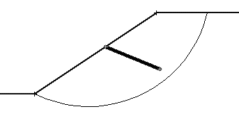
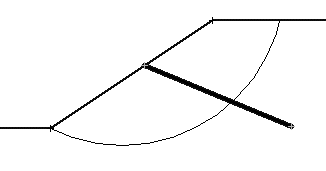
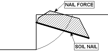
- For End Anchored support, Grouted Tiebacks, and Soil Nails, the orientation of the applied force is assumed to be parallel to the direction of the support, as shown in the previous figure.
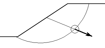
- For GeoTextiles or User Defined support, the support force can be applied tangent to the slip surface, parallel to the support, or at an angle which bisects the tangent and parallel angles. (The diagram is 2D but the actual implementation is 3D with respect to the base of a column).
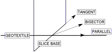
- For Micro Piles, the orientation of the support force can be tangent to the slip surface or perpendicular to the pile.
Note that the tangent to slip surface Force Orientation option (geotextiles, user-defined or micro piles) applies the support force in the plane of the column base, and against the sliding direction.
Magnitude of Applied Support Force
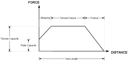
The magnitude of the applied support force will depend on the support properties entered in the Define Support Properties dialog. These are used to determine a Force Diagram for your support. A support Force Diagram simply represents the maximum available force which the support can apply to the sliding mass, at any point along the length of a support element.
- For End Anchored or Pile support, the Force Diagram is simply a horizontal line, since a constant support force will be applied, regardless of where a slip surface intersects an End Anchored or Pile support element.
- For GeoTextile, Grouted Tieback or Soil Nail support, the Force diagram is determined by considering each possible failure mode along the length of the support (Tensile, Pullout and Stripping, if applicable). The Failure Mode which generates the MINIMUM force determines the support force which can be generated at each point along the support.
- For User-Defined Support, the Force Diagram is entered directly by the user, support "properties" are not entered.
- For Grouted Tiebacks and Soil Nails, additional shear and compression failure modes can also be considered.
For detailed information on how the Force Diagram is determined for each support type, see the individual support type topics.
Interpretation of Support Force Diagrams
The user should appreciate that a support Force Diagram, as implemented in Slide3, does not necessarily represent the true state of stress or loading mobilized by a given support element. The Force diagram simply represents the maximum available force, which a given support element can theoretically apply to the sliding mass, at any point along its length. This is based on the assumptions described for each support type in Slide3.
Remember that the Slide3 analysis is a limit equilibrium analysis. Displacements and strains are not considered in such an analysis. In order to realistically model the interaction of support and slope, and to calculate actual strains and loading mobilized within the support, more sophisticated numerical analysis methods are required, such as finite element or finite difference methods.
The modelling of support in Slide3 is a simple but useful method, of accounting for the effect of the SUPPORT SYSTEM on the SLOPE, in a limit equilibrium slope stability analysis. It is not intended to model the effect of the SLOPE on the SUPPORT SYSTEM, and the support Force Diagrams should not be interpreted in this way.
Viewing the Support Force Diagram
The support force diagram for each support element in your model can be viewed in Results mode, with the Show Support Force Diagram option. The diagram will be displayed directly on the model, as shown in the previous figure.