Tension Crack
Where slopes exhibit high cohesion, it is possible for tension cracks to develop near the ground surface at the crest of the slope. While solving for the factor of safety, a slip surface passing through this region may have converge to a solution where tensile forces exist in the soil column bases, and/or the intercolumn forces become tensile.
The presence of significant tensile forces in a slipping mass may sometimes cause the converged factor of safety to be unrealistic. A common resolution to this issue involves vertically truncating the slip surface near the crest of the slope (Duncan et al. 2014).
In Slide3, tension cracks can be modelled using Tension Crack Surfaces, or via Automatic Tension Cracks.
Tension Crack Surfaces
The Tension Crack option allows you to define a surface which defines a tension crack zone. In Slide3, if any part of a slip surface is found above a Tension Crack surface, the slip surface will be vertically truncated by the Tension Crack surface. In other words, the region of the model above a tension crack becomes the tension crack zone.
There are two options available to define a Tension Crack surface:
- Add Tension Crack Surface, whereby an existing geometrical surface entity can be selected and converted into a Tension Crack Surface.
- Add Tension Crack by Location, whereby the coordinates of a Tension Crack Surface can be entered manually.
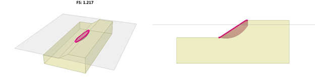
For instance, in the following model example a horizontal Tension Crack Surface is defined. The portion of the critical slip surface found above the tension crack is truncated.
Water Level
Note that when a slip surface is truncated by a tension crack, no lateral earth pressure forces are applied at the vertically truncated faces. However, hydrostatic forces may be applied if the Water Level is specified, as follows:
- Dry – no hydrostatic forces.
- Filled – water level is at the ground surface.
- Percent Filled – water level is a percentage of the way between the tension crack surface and the ground surface.
- Filled Below Elevation – water level is at the specified elevation.
- Filled to Depth – water level is at the specified depth below the ground surface
- Use Water Table – use the water table in the model to determine the water level
The hydrostatic forces will be applied perpendicular to the vertical side faces of the truncated columns.
Automatic Tension Cracks
- As an alternative to using tension crack surfaces, the program can create tension cracks automatically in the slip surfaces. This can be done via Materials > Tension Cracks > Automatic Tension Cracks…
The Enabled checkbox must be ON to use this feature.
Soil columns are removed from the analysis, thereby truncating the slip surface at its location, based on two angles:- Vertical tolerance angle
- Maximum angle to sliding direction
1. Its base inclined within the Vertical tolerance angle (in degrees) from the vertical plane, AND
2. The dip direction of its base is also aligned within the Maximum angle to sliding direction from the sliding direction.
In other words, soil columns are removed if their column bases are (1) very steep, and (2) the steepness is aligned with the slipping direction to produce tension.
If a soil column is removed in this manner, then the soil columns directly behind it, with respect to the direction of sliding, will also be removed. More specifically, if a ray drawn through a soil column in the direction of sliding intersects any soil column which has been removed due to the above two criteria, then the soil column is removed.
Theoretical Maximum Tension Crack Depth (z)
For a given soil with Mohr-Coulomb strength parameters c and f, and unit weight , the theoretical maximum tension crack depth z can be estimated from the following equations:
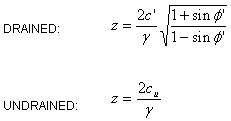
Note that if a slip surface is truncated too deep such that columns which would otherwise be in compression are also removed from the analysis, the computed factor of safety may not be realistic.
Further Discussion
The following rules should be noted when using tension cracks in complicated cases:
- If multiple tension crack surfaces exist in the model, then the bottommost tension crack at any given location will govern, along with its specified water level.
- If automatic tension cracks are specified and tension crack surfaces also exist in the model, then both will apply. The slip surface will be clipped based on the Tension Crack Surfaces first, followed by the automatic tension cracks.
References
Duncan, J.M., Wright, S.G., Brandon, T.L. 2014. Soil Strength and Stability 2ed. Hoboken, NJ: John Wiley & Sons Inc.