RSWebinar: Designing Cost-Effective Ground Improvement Solutions with Settle3 | June 7th, 2023 Register Now
 

Search Results

Anisotropic Surface Overview

The Anisotropic Surface option is only used in conjunction with the Generalized Anisotropic material strength model.

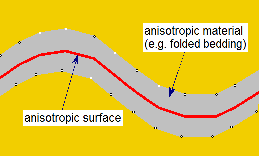
It allows you to define a 3D surface which is used to determine the local orientation of anisotropic material regions in which the direction of anisotropy changes with location. For example, a folded bedding layer as shown in the figure below. For simplicity this is illustrated in 2D however the actual surface is 3-dimensional.

Anisotropic Surfaces Figure
Anisotropic surface option, 2D schematic

There are two options available to define an Anisotropic Surface:

An Anisotropic Surface in conjunction with the Generalized Anisotropic material strength option, allows the Slide3 compute engine to determine the local orientation of folded anisotropic regions (for example), in order to apply the correct strength properties at any location.

Typically, an Anisotropic Surface should be defined near the "middle" of the corresponding anisotropic material region as shown in the above figure.

Portal Account Log Out Home Shopping Cart icon Click here to search our site Click here to close Learning Tech Support Documentation Info Chevron Delete Back to Top View More" PDF File Calendar Location Language Fees Video Click here to visit Rocscience's LinkedIn page Click here to visit Rocscience's YouTube page Click here to visit Rocscience's Twitter page Click here to visit Rocscience's Facebook page Click here to visit Rocscience's Instagram page Bookmark Network Scroll down for more Checkmark Download Print Back to top Single User Multiple Users RSLog RocFall3 CPillar Dips EX3 RocFall RocPlane RocSupport RocTopple RS2 RS3 RSData RSPile Settle3 Slide2 Slide3 SWedge UnWedge Commercial License Education License Trial License Shop safe & secure Money-back guarantee