Geosynthetics
The Geosynthetics support type can be used to model the various types of slope reinforcement which are used in the form of meshes, grids, strips, etc. There are a wide variety of such support systems, referred to as geotextiles or geo-fabrics, geo-grids, geo-synthetics. etc.
Geosynthetics are added to a model with the Add Geosynthetic option.
The term Geosynthetics will be used to refer to all forms of flexible planar reinforcement, which are used in the form of fabrics, meshes, grids, strips, membranes, etc, to reinforce slopes. This includes both synthetic (polymer) and metal (e.g. steel strip) reinforcement.
Strip Coverage
When a Geoynthetic is used to reinforce a slope, the material is placed in strips of a certain width. The Strip Coverage refers to the spacing of these strips, in the Out of Plane direction (i.e. along the slope). If the strips are laid continuously beside each other, with no gaps between adjacent strips, then the Strip Coverage = 100%. If the strips are not laid continuously (i.e. there are spaces between adjacent strips), then the Strip Coverage will be less than 100%. For example, if 4 meter wide strips were laid with a 2 meter spacing between each strip, then the Strip Coverage would equal 67% (i.e. 4 / (4 + 2)).
Strip coverage = (a / (a + b)) x 100
Tensile Strength
The Tensile Strength refers to the Tensile Strength (maximum load capacity, in force units) per meter width of the strip. This is also referred to as the Tear Strength when dealing with geo-fabrics for example.
Force Application
See the Force Application topic for a discussion of the significance of Active and Passive support force application in Slide3. For Geosynthetic support, you may wish to use Force Application = Passive, since there is normally no significant initial loading or tensioning of the support (although light pre-tensioning is sometimes applied, to optimize the effectiveness of the support).
Force Orientation
Because of the flexible nature of a Geosynthetic type of reinforcement, the orientation of the force which is applied to the slip surface is NOT always assumed to be parallel to the reinforcement. When the support begins to take on a load, due to displacements within the slope, the direction of the applied support force can be assumed to be:
- Tangent to Slip Surface
- Bisector of Parallel and Tangent (i.e. at an angle which bisects the tangent to slip surface orientation, and the parallel to reinforcement orientation)
- Parallel to Reinforcement
The following figure illustrates these options in 2D; the actual implementation is 3D with respect to the base of a column.
Anchorage
When Geosynthetic support is used, the support strips are normally anchored to the slope face, using some type of anchoring system. In addition, the embedded end of the geosynthetic may be anchored within the slope. When you add a geosynthetic support, you can choose which edge(s) of the geosynthetic is anchored in the Add Geosynthetic dialog (not the Support Properties dialog).
For a given strip of geosynthetic material, the significance of the Anchored option is as follows:
- If neither end is anchored, then all three failure mechanisms are possible (i.e. tensile, pullout or stripping)
- If both ends are anchored, then ONLY tensile failure is possible (pullout or stripping cannot occur)
- If only one end is anchored, then you can have tensile and either pullout or stripping modes
The potential failure modes of a geosynthetic are very important because they are used to determine the Force Diagram for the geosynthetic, which in turn determines the magnitude of the applied support force at any point along the geosynthetic. This is described later in this topic.
Shear Strength of Interface
The parameters entered here will govern the pullout and/or stripping force, which can be generated by the support.
There are three different methods of defining the shear strength of the interface. The preferred method can be selected with the Input Type dropdown:
- Friction Angle & Adhesion
- Coefficient of Interaction
- Friction Factor
Each input type is described below.
Input Type = Friction Angle & Adhesion
- The definitions of Adhesion and Friction Angle depend on the Strength Model which is used (Linear or Hyperbolic)
- For analyses involving pore pressure, the normal stress takes into account the pore pressure. Therefore the Adhesion and Friction Angle can be considered effective stress parameters.
- Also see the important note below, regarding the interpretation of the pullout strength parameters for a GeoTextile, and for a Geo-Grid.
Adhesion
- If the Strength Model = Linear, then the Adhesion defines the shear strength of the geosynthetic / soil interface, at zero normal stress, according to the Mohr-Coulomb strength envelope.
- If the Strength Model = Hyperbolic, the Adhesion defines the shear strength of the geosynthetic / soil interface, at high normal stresses. See below for details.
Friction Angle
- If the Strength Model = Linear, then the Friction Angle defines the stress-dependent shear strength of the geosynthetic / soil interface, for normal stress greater than zero. The normal stress (i.e. stress perpendicular to the support) is the result of the weight of soil overburden, and also any other forces due to external or seismic loading.
- If the Strength Model = Hyperbolic, then the Friction Angle defines the initial tangent angle of the hyperbolic shear strength envelope, at zero normal stress. See below for details.
Shear Strength Model (Linear)
If the Shear Strength Model = Linear, this means that the Shear Strength (i.e. Pullout Strength) of the support is determined from the Mohr-Coulomb relationship for the strength of an interface:
 = interface adhesion,
 = interface friction angle, entered as the Pullout Strength parameters.
For analyses involving pore pressure, the normal stress takes into account the pore pressure. Therefore the Adhesion and Friction Angle can be considered effective stress parameters. See the additional important note below, regarding the interpretation of the pullout strength parameters and the normal stress for a geosynthetic.
Shear Strength Model (Hyperbolic)
When the Shear Strength Model = Hyperbolic, the Shear Strength (i.e. Pullout Strength) of the support will be determined from the following equation:
 and
and in Equation 2. The following figure illustrates a hyperbolic shear strength envelope.
 is defined as the shear strength at
 .is defined as the friction angle at
 .
.If the Strength Model = Hyperbolic, the Adhesion and Friction Angle which you enter as the Pullout Strength parameters must correspond to these definitions.
For analyses involving pore pressure, the normal stress takes into account the pore pressure. Therefore the Adhesion and Friction Angle can be considered effective stress parameters.
See the additional important note below, regarding the interpretation of the pullout strength parameters and the normal stress for a geosynthetic.
Input Type = Coefficient of Interaction
In this case the shear strength of the interface is defined as follows:
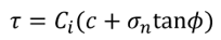
Where Ci is the coefficient of interaction, and c and φ are the cohesion and friction angle of the material in which the geosynthetic lies. These are automatically sampled at increments along the geosynthetic. When they are not available, equivalent values are calculated.
Coefficient of Interaction
The coefficient of interaction is used to take some fraction of the shear strength of the surrounding material as the shear strength of the interface. A value of 0 would take no shear strength, whereas a value of 1 would use the full shear strength of the surrounding material.
Input Type = Friction Factor
In this case the shear strength of the interface is defined as follows:

Where F* is the friction factor.
Friction Factor
The friction factor input by the user is multiplied by the normal stress along the geosynthetic in order to obtain the shear strength of the interface.
Material Dependent Pullout Strength
The Material Dependent checkbox allows you to define the pullout strength of the geosynthetic according to the material(s) which the support passes through. In order to use this option:
- Select the Material Dependent checkbox, and select the Define button.
- You will see the Define Pullout Strength dialog. In this dialog, select the Add
 button, for each material that you wish to define the pullout strength for.
 - For each material, use the mouse to select a Material and enter the Adhesion and Friction Angle for the material.The Material Names correspond to the materials you have defined in the Define Material Properties dialog).
- Any material which you have NOT included in the Define Pullout Strength dialog, will use the Pullout Strength parameters which you have entered in the Define Support dialog.
When you are finished customizing the Pullout Strength parameters for all the required materials, select OK in the Pullout Strength dialog.
Interpretation of Geosynthetic Shear Strength Parameters
In order to correctly interpret the definition of the Adhesion and Friction angle parameters used to define the Pullout Strength of a geosynthetic in Slide3, it is important to understand the following:
- The Pullout Strength parameters (Adhesion and Friction Angle) define the shear strength of the geosynthetic/Soil interface.
- However, a geosynthetic embedded in soil has TWO interfaces with the soil. When pullout occurs, the shear strength of BOTH interfaces must be accounted for by the pullout force.
For example, consider a unit width of geosynthetic, with Length = L and Pullout Force = P.
Pullout force and shear strength of a geosynthetic, Strength Model = Linear (Mohr-Coulomb)
The relationship between the pullout FORCE (P), and the SHEAR STRENGTH ( ), is therefore:
 (or
(or  )
)When the pullout and stripping forces are calculated for a geosynthetic in Slide3, a factor of 2 is included in the force calculation, in order to account for the shear strength of BOTH sides of the geosynthetic (see below for equations).
This interpretation of geosynthetic pullout strength is applicable to geotextiles, geo-fabrics, metal strips, etc., which have a 100% contact area with the soil (i.e. there are no "holes" in the material, and the geosynthetic/Soil interface is continuous).
When dealing with Geo-Grids and similar products, which have a significant area of soil-soil contact, through the holes in the Geo-Grid, this relationship is a simplification of the true failure mode.
- For Geo-Grids shear resistance is not uniform along the length of the material (i.e. Adhesion and Friction Angle are different for the geosynthetic / Soil interface, and the soil/soil interface).
- Furthermore, the pullout capacity is mainly developed as the bearing earth pressure against the transverse elements of the grid [Forsman & Slunga (1994)].
However, for Geo-grids, the "apparent" interface shear strength parameters (Adhesion and Friction Angle) can be calculated, and these are sufficient for the purposes of modelling in Slide3.
Normal Stress
In general, the normal stress which is used in the shear strength equations (Eqn.1 or Eqn.2) will vary along the length of a geosynthetic. The normal stress is determined as follows:
- Each geosynthetic support element is first subdivided into elements.
- For each subdivision along the geosynthetic, the vertical stress is determined from the overburden stress, as well as any vertical component of external loading which acts on the slope above the geosynthetic.
- In most cases, geosynthetics are placed horizontally, therefore the normal stress is equal to the vertical stress. In cases where geosynthetics are not placed horizontally, hydrostatic stress is assumed, so again, the normal stress is equal to the vertical stress.
- For analyses involving pore pressure, the normal stress takes into account the pore pressure, and is, therefore, the effective normal stress.
- The normal stress is then used to compute the frictional pullout force which can be contributed by each subdivision along the length of the geosynthetic. The applicable shear Strength Model will be used (Linear or Hyperbolic).
Anisotropic Tensile Strength
The tensile strength of a geosynthetic can be specified to act in an anisotropic manner in which the tensile strength is dependent on the orientation of the geosynthetic and the shear plane acting through it. The following options can be selected in the Anisotropic Model dropdown:
- Linear
- Cosine-1
- Cosine-2
- Cosine and Sine
- Critical Angle
- Linear Critical Angle
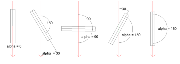
- In general, the calculated strength is the projected strength of the geosynthetic plane onto the shear plane based on the offset between the two planes.
- The geosynthetic assumes the specified max allowable tensile strength and min allowable tensile strength act in the machine direction (parallel to plane) and cross-machine direction (perpendicular to plane) respectively. The global orientation of the geosynthetic does not affect the calculations of strength, only it’s relative angle from the shear plane. For example, alpha = 30 degrees gives equivalent strength to alpha = 150 degrees
Linear
- If the Anisotropic Model = Linear, then the strength is defined by the following equation:

Cosine-1
- If the Anisotropic Model = Cosine-1, then the strength is defined by the following equation:

Cosine-2
- If the Anisotropic Model = Cosine-2, then the strength is defined by the following equation:

Cosine and Sine
- If the Anisotropic Model = Cosine and Sine, then the strength is defined by the following equation:

Critical Angle
- If the Anisotropic Model = Critical Angle, then the strength is defined by the following equation:


Linear Critical Angle
- If the Anisotropic Model = Linear Critical Angle, then the strength is defined by the following equation:


where
- alpha (α) – angle between the failure direction and orientation of geosynthetic strip
- T(α) – tensile force of geosynthetic as a function of alpha
- Tmax – specified max allowable tensile strength acting in machine direction
- Tmin – specified min allowable tensile strength acting in cross-machine direction
Further Reading
Further information regarding geosynthetic uses and properties, can be found in Jewell (1996). In particular, Chapter 4 of this reference provides insight into the behaviour of geosynthetics and GeoGrids in reinforced slopes, and the significance of the "bond coefficients", which are commonly used to describe the shear strength of the geosynthetic/Soil interface.
Implementation of Geosynthetic Support in Slide3
The Geosynthetic properties which are entered in the Support Properties dialog, are used to determine a Force Diagram for a geosynthetic as described below.
Consider a geosynthetic which intersects a slip surface as shown below (2D diagram).
Li = length of geosynthetic within sliding mass
Lo = length of geosynthetic embedded beyond slip surface
Geosynthetic parameters
A = Strip Coverage (%)

a = Interface Adhesion (force / area)
T = Tensile Strength (force / width)
For Geosynthetic support in Slide3, three failure modes are possible, depending on the Anchor settings of the edges of the geosynthetic.
- Tensile (always possible, for all Anchor settings)
- Pullout (if embedded edges are not anchored)
- Stripping (if slope face edge is not anchored)
Pullout
For a geosynthetic, pullout can only occur if the embedded end is NOT anchored (i.e. Anchorage = Slope Face or Anchorage = None). The maximum pullout force which can be mobilized, PER UNIT WIDTH OF SLOPE, is given by:
where the shear strength is given by Eqn.1 if the Strength Model = Linear (Mohr-Coulomb), or Eqn.2 if the Strength Model = Hyperbolic.
Material Dependent Shear Strength
If the geosynthetic Pullout Strength is specified as Material Dependent, then the Pullout Force is determined by integrating along the length of the geosynthetic, to determine the force contributed by each segment of the geosynthetic which passes through different materials. In this case, Equation 3 will use the appropriate Adhesion and Friction Angle for each material.
Tensile Failure
Tensile Failure of a geosynthetic is ALWAYS a possible failure mode, regardless of the Anchor settings. At any point along the geosynthetic, the maximum tensile load, PER UNIT WIDTH OF SLOPE, which can be mobilized by the geosynthetic, is simply given by:

Stripping
Stripping is the term used in Slide3 when support failure occurs by the sliding mass "stripping" off of the support (i.e. the support remains embedded in the slope).
where the shear strength is given by Eqn.1 if the Strength Model = Linear (Mohr-Coulomb), or Eqn.2 if the Strength Model = Hyperbolic.
Force Diagram
At any point along the length of a geosynthetic, the magnitude of the force which will be applied to a slip surface which intersects the geosynthetic is given by the minimum of the Tensile, Pullout (if applicable), and Stripping (if applicable) forces. This depends on the setting of the Anchorage option:
Anchorage = None Applied Force = min (F1, F2, F3)
Anchorage = Slope Face Applied Force = min (F1, F2)
Anchorage = Embedded End Applied Force = min (F2, F3)
Anchorage = Both Ends Applied Force = F2
In most cases, a geosynthetic will be anchored to the slope face, but not anchored within the slope (i.e. Anchorage = Slope Face). In this case, the Force Diagram for a geosynthetic will resemble the following figure, in which the only failure modes are Tensile and Pullout.
References
- Esterhuizen, J., Filz, G.M. and Duncan, J.M., Constitutive Behaviour of Geosynthetic Interfaces, Journal of GeoTechnical and Geoenvironmental Engineering, October 2001, pp 834-840.
- Forsman, J. and Slunga, E., The Interface Friction and Anchor Capacity of Synthetic Georeinforcements, Fifth International Conference on Geotextiles, Geomembranes and Related Products, Singapore, September 1994.
- Jewell, R.A., Soil Reinforcement With Geotextiles, Special Publication 123, Construction Industry Research and Information Association, London, 1996.