RSPile
The RSPile support type in Slide3 works in conjunction with the Rocscience pile analysis program RSPile (version 3.008 or later).
- Pile properties are defined in the RSPile program, which computes the mobilized lateral and/or axial resistance along the length of a pile, for a given soil geometry and loading conditions.
- The pile support force used in the Slide3 analysis is then determined by the location and angle of the slip surface intersection with the pile.
The methodology for determining the reaction of the pile against the slipping surface is outlined at the beginning of the RSPile Integration tutorial.
RSPile File
If you have already defined properties and saved an RSPile file, then you can read this file by selecting the Choose file button.
If you are defining a new RSPile file, then select the Run the RSPile Utility option  , to define the pile and soil properties and save the file.
Matching Materials
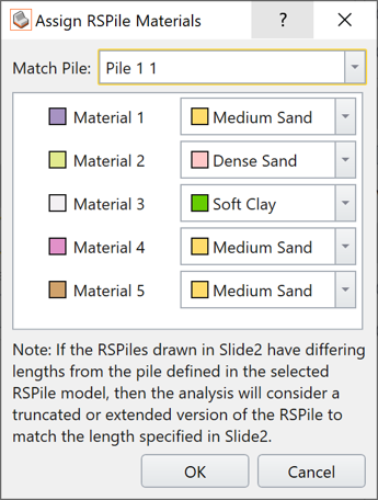
During the analysis of the pile, the layers of materials intersected by the pile in the Slide3 model are considered. Since the analysis of the pile within these layers requires material property definitions relating to pile analysis, the properties will be taken from the RSPile file. As such, for each material intersected by the pile in the Slide3 model, a corresponding material within the RSPile file needs to be specified for the analysis.
When a file is chosen, the Match RSPile Materials dialog will pop up. You will be prompted to (1) select the pile in the RSPile file that you want to use for the current support, and (2) match the material definitions between the RSPile file and the Slide3 file.
You can always go back and change the matched properties (via Match Materials) if you did not like the original arrangement.
During the analysis, the length of the pile and thicknesses of the soil layers in Slide3 will override those defined in the RSPile model, and the material properties defined in the RSPile model will be used for the computations.
Soil Displacement
The Soil Displacement is the allowable soil displacement along a slip surface at the point of intersection with a pile.
- Maximum - this allows you to enter a maximum (limiting) value of the imposed soil displacement (mm or inches).
- Ultimate - in this case, the soil displacement is allowed to increase until the yielding of the pile.
The soil displacement is a vector applied at the location of the intersection between the pile and the slip surface. Its dip direction is in the plane direction of sliding, and its dip is such that it tangents to the slip surface at the location of the pile. This displacement is an imposed initial soil displacement condition during the RSPile analysis.
Force Application
For RSPile support, the default method of Force Application = Active. See the Force Application topic for a discussion of the significance of Active and Passive support force application in Slide3.
Axial and Lateral Analysis
Within the RSPile project settings, there are options to specify whether the pile will be considered to be Axially Loaded, Laterally Loaded, or Axially/Laterally Loaded.
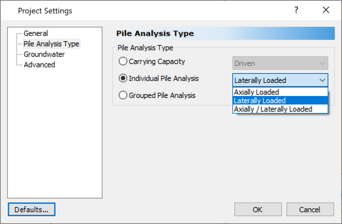
If the pile is axially loaded, then the axial component of the soil displacement will be applied to the pile, and the axial reaction is applied onto the slip surface.
If the pile is laterally loaded, then the components of the soil displacement along the two lateral axis directions, X’ and Y’, will be determined and applied onto the pile. These axes are shown in both the RSPile and Slide3 interfaces. The X’ and Y’ reactions will be applied laterally in Slide3 onto the slip surface in their corresponding directions.
Batter and Ground Slope Modifiers
For the lateral analysis of certain materials, the batter angle and ground slope at the surface near the pile in the direction of slippage affect the soil resistance for shallow slip surfaces calculated in RSPile (see Laterally Loaded Piles Theory Manual in the RSPile documentation).
Three options are provided in Slide3 to account for these angles:
- Apply Batter and Ground Slope Modifiers: If toggled OFF, slope angle modifiers will be ignored during calculations of lateral soil resistance. If toggled ON, then one of the following two options must be selected.
- Calculate from Slide3 model: the pile batter and ground slope angles will be calculated based on the geometry of the pile and ground topography in the Slide3 model. The ground slope is determined along the X’ and Y’ directions.
- Use RSPile file values: the pile batter and ground slope angles in the RSPile file that you have selected will be adopted during the calculation of the soil resistance.
TIP: By default, RSPile performs one pile analysis for each pile defined in the Slide3 model. However, if there are piles that go through identical soil layers and have identical geometry, ground slope, batter angle, then Slide3 will save time by skipping the subsequent analyses for the identical piles. If there are many piles in the model and the soil layers that intersect have the same thickness, it may speed up the analysis to either toggle OFF Apply Batter and Ground Slope Modifiers, or to Use RSPile file values.
Add RSPile Support
See Add Support for information on how to add a support element in Slide3. The process for inserting an RSPile is the same as with any other support type, except that the rotation of the pile about its own longitudinal axis can affect the reaction of the pile.
The rotation of the RSPile about its own longitudinal axis can be defined via Add Support > Properties > Define Orientation
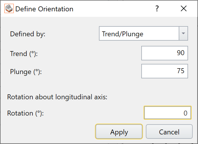
The trend and plunge of the pile are based on the sign convention described here.
The rotation of the pile about its own longitudinal axis is measured in degrees counter-clockwise. For vertical piles, a rotation of zero degrees corresponds to the Y’ axis pointing in the Y direction. For battered piles, a rotation of zero corresponds to the Y-axis pointing in the trend direction.
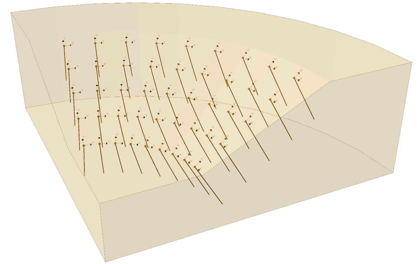
When the orientation of the pile is defined, the X’ and Y’ vectors as they would appear in RSPile will be rendered in the Slide3 interface.