Block Model
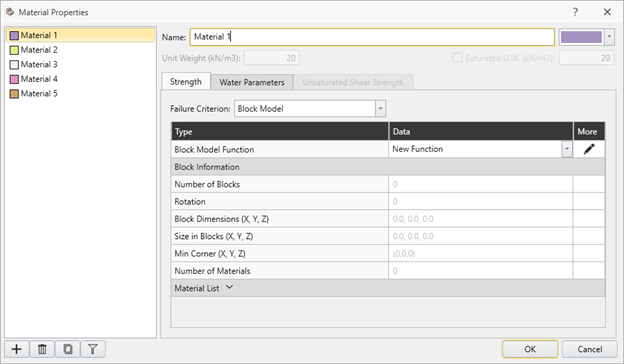
Users can select Block Model in Slide3 as failure criterion. They can import a Block Model by going to the Material Properties dialog, switching the Failure Criterion to Block Model, and selecting the edit button in the More column of the grid.
When importing a block model, there is an option to import block-level values for the following parameters:
- Dip
- Dip Direction
- UCS
- GSI
- mi
- D
- Cohesion
- Friction Angle
This still means that the material is the same. For example Material A can have all constant parameters except for GSI which varies at the block level.
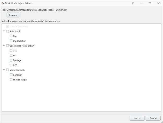
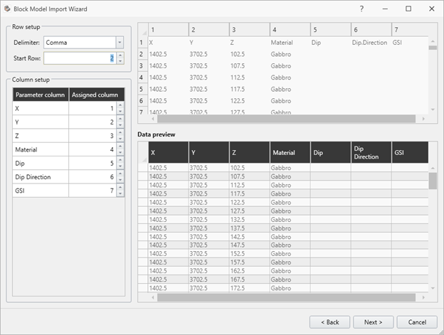
If any of these parameters are selected, they will be expected to have values imported for them in the following import page. For example, if Dip, Dip Direction, and GSI are selected, columns from the csv are expected to be assigned to these parameters. Any of these options can be selected in any combination.
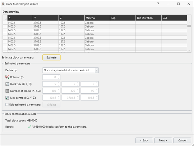
The next phase of importing the block model requires validating the parameters. First, estimate must be performed. Values will automatically populate in the parameters section, and at this point they can be edited by using the checkbox called “Edit estimated parameters”. It is recommended to always validate edited values. Unless all blocks conform to the entered parameters, it will not be possible to continue with the import.
All ranges for the optional parameters must also be valid, otherwise an error will be shown at the end of importing and the import must either be revised or cancelled.
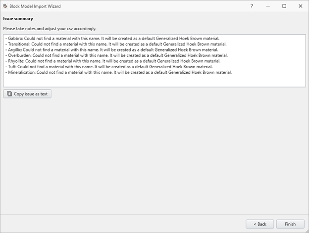
For the final step of the import process, if there are any missing materials a list of these materials will be shown and added to the materials in the project. These materials will always be created as a default Generalized Hoek-Brown material, so the properties of them should be changed as needed afterwards. If there are no materials that need to be added, this next step will just show an “Imported Successfully” message.
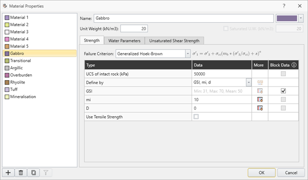
Once back in the Material Properties dialog, you will see that the Block Model material has information about the block model displayed in the grid:
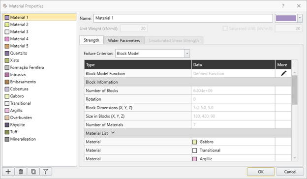
The block model can be changed at any point by clicking on the edit button in the More column. This will start the import process again.
If the imported block model was imported with block-level data, now it can be used by materials.
Below is a list of each of the parameters along with a list of each Failure Criterion they can be used with:
- Dip – Anisotropic Strength, Generalized Anisotropic
- Dip Direction – Anisotropic Strength, Generalized Anisotropic
- UCS – Generalized Hoek-Brown
- GSI – Generalized Hoek-Brown
- Mi – Generalized Hoek-Brown
- D – Generalized Hoek-Brown
- Cohesion – Mohr Coulomb,
- Friction Angle – Mohr Coulomb, Undrained
Block Data will become available in a fourth column in the table of the associated materials. For instance, if just GSI block-level data was imported, this is how the grid will appear:

In this case, the checkbox will be enabled for GSI but not for the other parameters.
For Undrained materials, cohesion block-level data is only available when the Cohesion Type is constant.
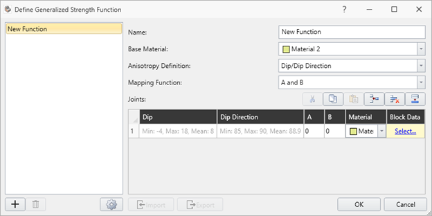
For Generalized Anisotropic block-level parameters, it can be selected by clicking the button on the right-most column in the grid.
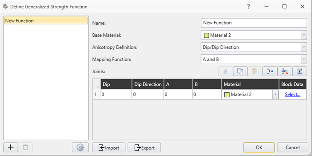
Here you will be able to see the options for importing Dip and/or Dip Direction (as long as both were imported with the block model).
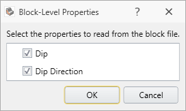
If any parameters are selected, they will be displayed with the Min, Max and Mean values retrieved from the block model file.
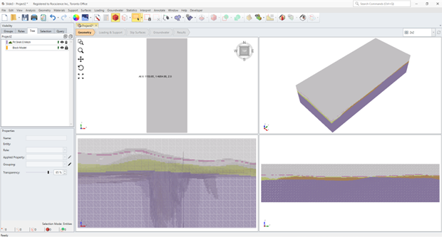
When a piece of geometry using the block model material is added, a Block Model node will be created, which will be all of the blocks from the block model.
When the Block Model node is selected, in the properties pane there is an option to change the rendering method between mesh and point cloud options.
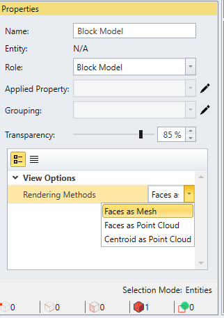
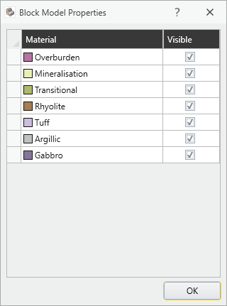
Additionally, if the pencil icon button next to the Applied Property is clicked, a dialog will appear which will allow you to turn on/off the visibility of different materials within the block model.
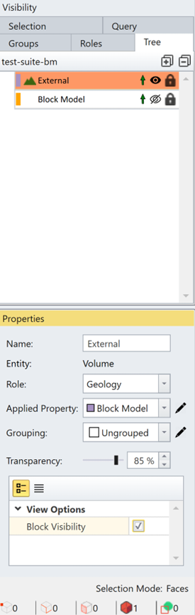
Once there is an external piece of geometry that uses the block model material, the block model projection will occur. The projection is a view of what the block model actually looks like when applied to the external.
In order to be able to select faces, edges, or vertices on the external, the block visibility on the external must be turned off. This option is available under the Properties pane when the external is selected.
The above way is the recommended way of using the block model with an external. Another option is to use the Geometry -> Create External From Block Model option. This will create the external based on the geometry defined in the block model file that was imported into one of the material properties. This process can take a long time, depending on the complexity and size of the block model.
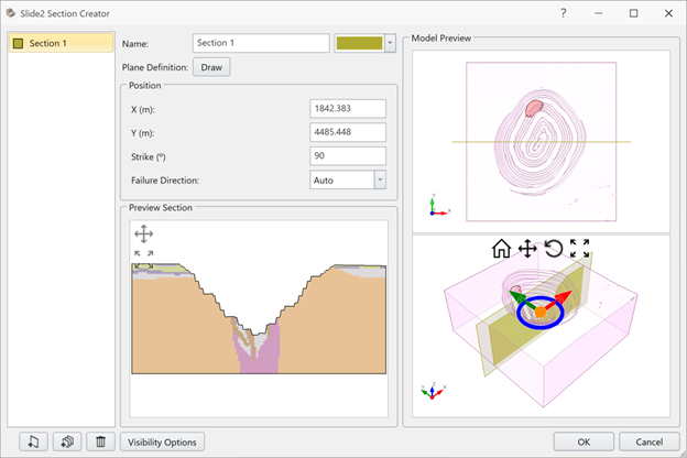
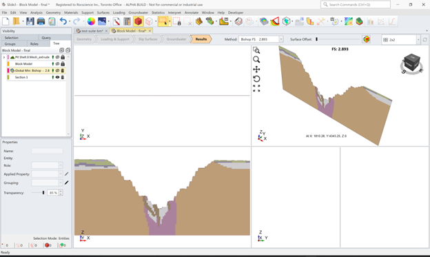
Once the block model external is created, it is possible to create sections to export and compute in Slide2. By going to Geometry -> Sectioning Tools -> Slide2 Section Creator, sections can be created that can then be exported to Slide2. In the section creator dialog, the projection of the block model on the section(s) geometry is visible.
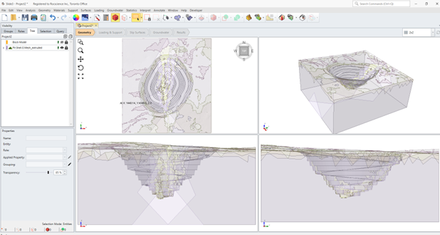
After creating the section geometry, by turning off all other geometry in the visibility window, the projection of the block model is visible on the section(s) within the viewport.
- Block model materials cannot be used in Generalized Anisotropic strength functions.
- Block model materials cannot be used in Boreholes.
- Only one block model material may be defined in a project.
- When a Generalized Anisotropic material is used in the active Block Model material function, only one joint can be defined in the Generalized Anisotropic function.