Anisotropic Linear Strength
The Anisotropic Linear strength model, proposed by Snowden engineering in Australia (Mercer, 2012; Mercer, 2013), allows you to define a material with the following anisotropic strength characteristics:
- Bedding plane cohesion and friction angle (c1 , phi1) defines the minimum shear strength
- Rock mass cohesion and friction angle (c2 , phi2) defines the maximum shear strength
- Angle of bedding plane orientation (theta) from horizontal
- Parameters A and B define a linear transition from bedding plane strength to rock mass strength, with respect to shear plane orientation.
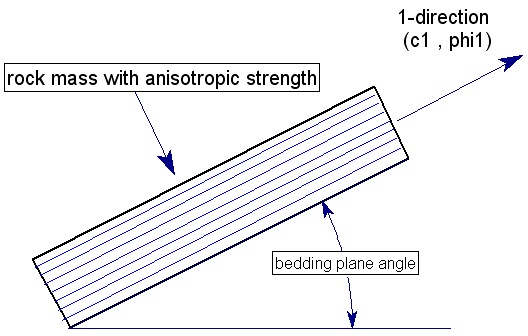
The Anisotropic Linear model is based on the Mohr-Coulomb criterion and assumes that the minimum shear strength occurs in the direction of the bedding planes. In the following figure, the 1-direction represents the orientation of the bedding planes, with cohesion (c1) and friction angle (phi1). The 1-direction can be defined by a constant Angle or by an anisotropic surface according to the Anisotropy Definition option (see below for details).

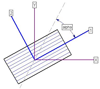
Consider an arbitrary plane which makes an angle alpha with respect to the 1-direction, as shown in the following figure. This represents the orientation of an individual slice base, in the Slide2 analysis.

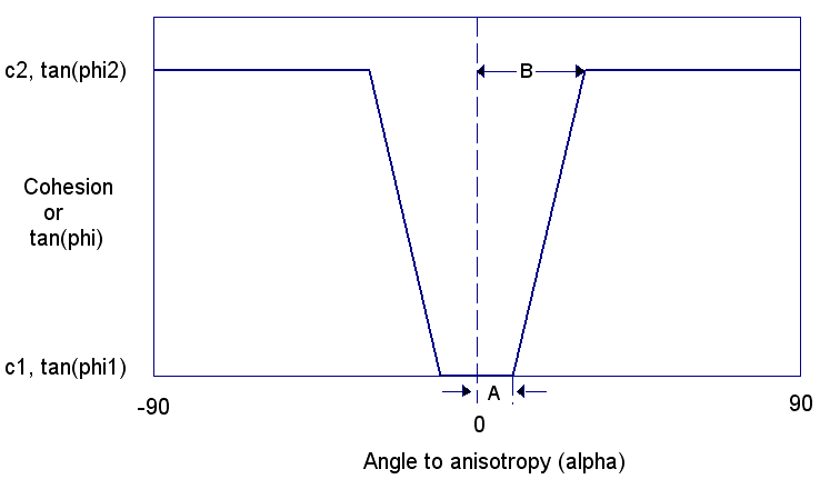
The relationship between shear strength and alpha angle is illustrated in the following figure. Based on the anisotropic input parameters (c1, phi1, c2, phi2, A, B, theta), the cohesion and the tangent of the friction angle can be computed for any plane orientation.
- The parameter A defines an angular range on either side of the bedding plane orientation, for which the bedding plane shear strength only applies (i.e. c1, phi1).
- The parameter B defines the angular range (B - A) over which the increase from bedding plane to rock mass shear strength takes place. The transition is assumed to be linear.
- For orientations outside of the B range, the rock mass shear strength only applies (i.e. c2, phi2).

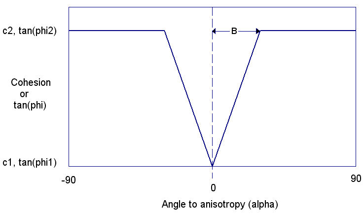
If angle A is zero, then the anisotropic linear strength function will appear as follows. In this case, the minimum shear strength is only applied if the plane orientation is exactly parallel to the bedding orientation.

The Anisotropic Linear strength model reportedly provides better estimates of anisotropic rock mass strength for certain types of bedded rock mass formations, compared to the Slide2 anisotropic strength model described on the Strength Type page. This is due to the ability to model the rapid transition from bedding plane strength to rock mass strength, as the shear plane angle deviates from the bedding plane angle.
Anisotropy Definition
For the Anisotropic Linear strength model there are two methods of defining the direction of the anisotropy:
- Angle
- Surface
If the Anisotropy Definition = Angle then the direction of anisotropy is constant and defined by a single angle which is entered in the Angle (ccw to 1) edit box. The definition of the angle is illustrated in the figures above.
If the Anisotropy Definition = Surface then the direction of anisotropy can be variable and defined by an Anisotropic Surface. Select the desired anisotropic surface from the Anisotropic Surface list box.
Angle (ccw to 1)
If Anisotropy Definition = Angle then the direction of anisotropy is constant and entered in the Angle (ccw to 1) edit box. See above figures.
Anisotropic Surface
If Anisotropy Definition = Surface you must select a surface from the Anisotropic Surface list box. If the list box is disabled, this means that you have not defined any anisotropic surfaces. You must use the Add Anisotropic Surface option to define an anisotropic surface. See the Anisotropic Surface Overview topic for more information.
Computation of Anisotropic Shear Strength
For a given plane (slice base) which makes an acute angle ![]() with respect to the bedding plane orientation, the cohesion and friction angle are calculated as follows for the Anisotropic Linear model.
with respect to the bedding plane orientation, the cohesion and friction angle are calculated as follows for the Anisotropic Linear model.
First, a dimensionless parameter t is computed.

 is the absolute value of the angle
  .
. and friction angle
  of the plane are computed using the following equations.


