Weak Layer Overview
A Weak Layer boundary allows you to model a potential sliding interface by defining a polyline with assigned strength properties. This is useful for modelling very thin weak layers or interfaces with low strength properties, such as a geomembrane interface.
ADD WEAK LAYER
To add a weak layer to a model use the Add Weak Layer option.
How the weak layer works
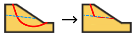
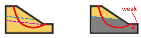
A weak layer works to crop or clip the failure surface. When failure surface starts at the ground surface, it continues down into the soil, and if it hits a weak layer it will traverse along the weak layer until either:
- It hits the ground surface.
- It finds the original slip surface intersection on its way back to the ground surface.
- It subducts another weak layer with higher elevation
WEAK LAYER HANDLING OPTIONS
The following options (available via Slip Surface Options > Weak Layer Handling) will determine the logic for clipping the slip surfaces to the weak layers.
See Tutorial 22 – Weak Layers for more information on how to use this feature.
Always snap to highest layer
- Every weak layer that touches a given slip surface will clip it.
- In the case of multiple weak layers, the clipped surface will follow the highest weak layer.
- Using this method will save computational time if you know that only the top weak layer needs to be analyzed.
Automatic Case Generation
For a given slip surface and the weak layers that it touches, the program will determine all applicable combinations of toggling each weak layer on and off and attempt to evaluate the factor of safety for each case.
Heuristic
- Toggles the weak layers on and off during the random search process (available only for Particle Swarm Optimization and adapted from Kennedy and Eberhart (1997)).
- Weak layers producing lower factors of safety tend to remain toggled more often as the search progresses.
- It is much more efficient than the Automatic case generation for models with many weak layers.
ENTIRE WEAK LAYER
SUPPRESS WEAK LAYER
It is possible to completely exclude a weak layer defined in the model from the analysis, without having to delete it. You can do this by checking off the “Suppress” checkbox in the weak layer properties.
Note that active weak layers found outside of the external geometry can cause slip surface errors during discretization if they are located above the slip surface. Ensure that these are suppressed.
VERTICAL WEAK LAYERS
Slide attempts to cut slip surfaces using the weak layers that they intersect. Sometimes, discretization issues can occur when these cuts are vertical or near-vertical.
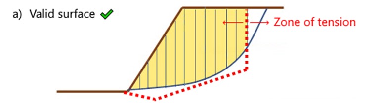
Case a) Vertical cuts in tension zones
In many cases, vertical weak layers can produce valid slip surfaces for analysis. For example, the slip surface below (blue) is cut vertically in a zone of tension by the vertical face of a weak layer (red). The resulting slip surface and slices/columns for analysis are highlighted in yellow. This slip surface is valid because, in the zone of tension, no reaction force is assumed to be exerted by the soil to the right side of the cut.
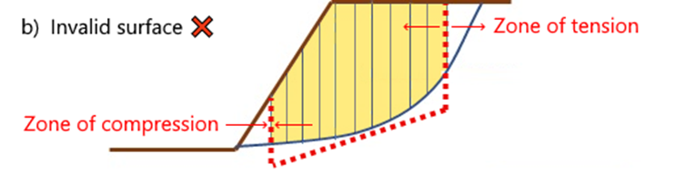
Case b) Vertical cuts in compression zones
Suppose the weak layer is modified such that it also cuts the slip surface in a zone of compression near the base of the slope, as shown below. The resulting slip surface is invalid, because the restoring lateral force exerted by the soil left of the cut in the zone of compression is non-zero, and cannot be determined using limit equilibrium methods.
If this case is ever encountered, Slide will report Error -149 and prompt a warning when viewing the results. However, if the desired analysis is for the slip surface to pass through (and effectively ignore) the weak layer in the zone of compression, then there are several ways to bypass the error:
- Replace the vertical faces of the weak layers with Tension Cracks, which vertically cut the slip surfaces only if the soil is in tension at those locations.
- Alter or delete the left vertical portion of the weak layer so that it does not vertically intersect the slip surface (like case (a)).
- Split up the weak layer geometry into separately defined weak layers, and use the Weak Layer Handling feature.
- Use more advanced techniques such as finite element analysis in RS2 & RS3, which consider the behavior of the entire slope.
Case c) Vertical cuts in compression zones
Near-vertical weak layers can also create columns with very steep base angles, which are known to induce numerical instability in limit equilibrium methods and should be avoided if possible.
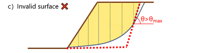
If the base angle of a column, θ, exceeds the maximum allowable angle, θmax, then the slip surface will be discarded with Error -126. The default value of θmax is 80° can be changed via Project Settings > Advanced. Weak layers with inclinations greater than this value are not recommended they can otherwise create convergence problems and incorrect results.
CONVEX SURFACES ONLY CHECKBOX
MANY WEAK LAYERS OR GEOSYNTHETICS WITH SLIDING
Weak layers here constitutes both weak layers and geosynthetics that have the sliding option on.
If you have defined more than 20 weak layers and selected Weak Layer Handling = Automatic Case Generation in Surfaces > Surfaces Options, Slide2 will not allow you to compute. This is because the Automatic Case Generation option considers different combinations of weak layers and doing this for over 20 weak layers is a very heavy computation.
If you have defined more than 10 (and less than 20) weak layers, and selected Weak Layer Handling = Automatic Case Generation in Surfaces > Surfaces Options, Slide2 will allow you to compute but warn you that the computation might be slow.
As a general rule of thumb, if you are working with a lot of weak layers, it is recommended to use the Weak Layer Handling = Heuristic option found in the Particle Swarm Search method. This option is compatible with any number of weak layers and does not slow down computation.