Anisotropy - Two Planes
1.0 Introduction
This model demonstrates a simple homogeneous slope, with TWO planes of anisotropy at different orientations. The Generalized Anisotropic Strength function is used. For more details regarding definition of anisotropic plane with strength parameters, please refer to Generalized Anisotropic Overview.
2.0 Material with Two Anisotropic Planes
This model demonstrates a simple homogeneous slope, with TWO planes of anisotropy at different orientations. The Generalized Anisotropic Strength function is used.
- Select File > Recent > Tutorials in the menu and open the file Anisotropy – Two Planes
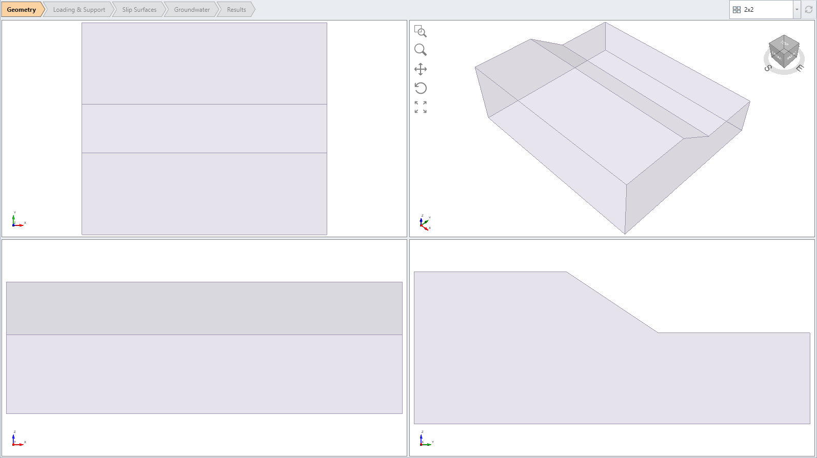
The model is a single material 2D slope extruded to 3D. - Select Materials > Define Materials

Notice the four materials defined: anisotropic material, rock mass, weak joint planes, stronger plane.
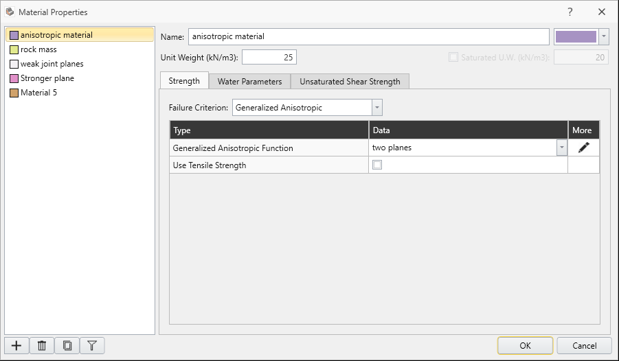
- For the anisotropic material, select the Edit
 button beside the Generalized Function combo box.
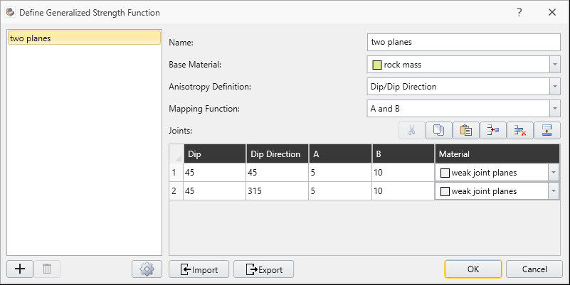
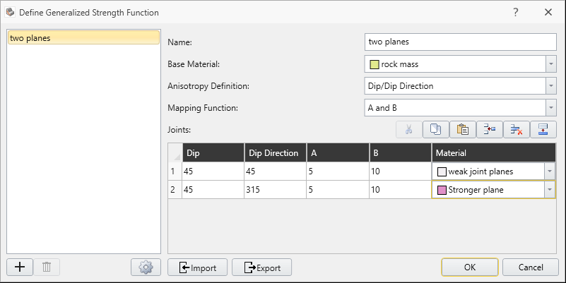
- Make sure the following parameters are entered.
- Anisotropy Definition = Dip/DipDirection
- Mapping Function = A and B
- Two anisotropic planes are defined
- Dip = 45 Dip Direction = 45
- Dip = 45 Dip Direction = 315
- A parameter = 5 (both planes)
- B parameter = 10 (both planes)
- Base Material = “rock mass”
- Anisotropic plane Material = “weak joint planes”

 from toolbar.
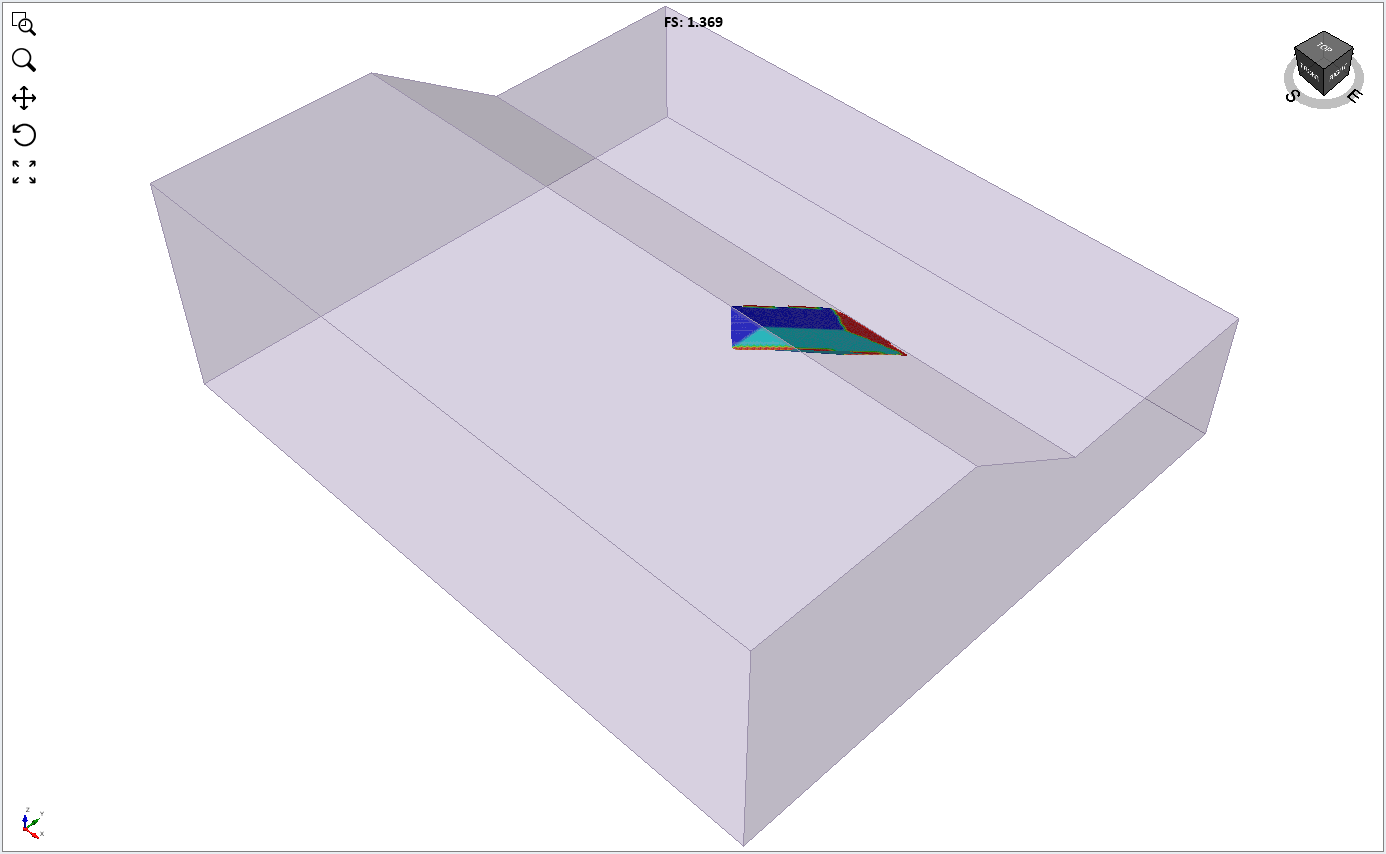
 For the Bishop method, the global minimum surface should appear as follows. Safety factor = 1.2. Base Normal Stress contours are displayed in the following figure.
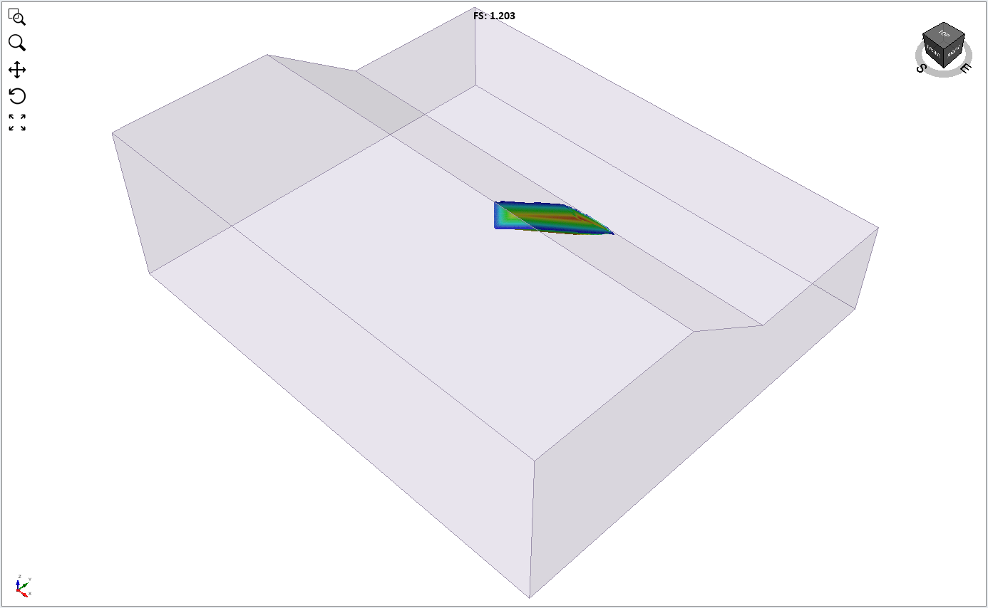
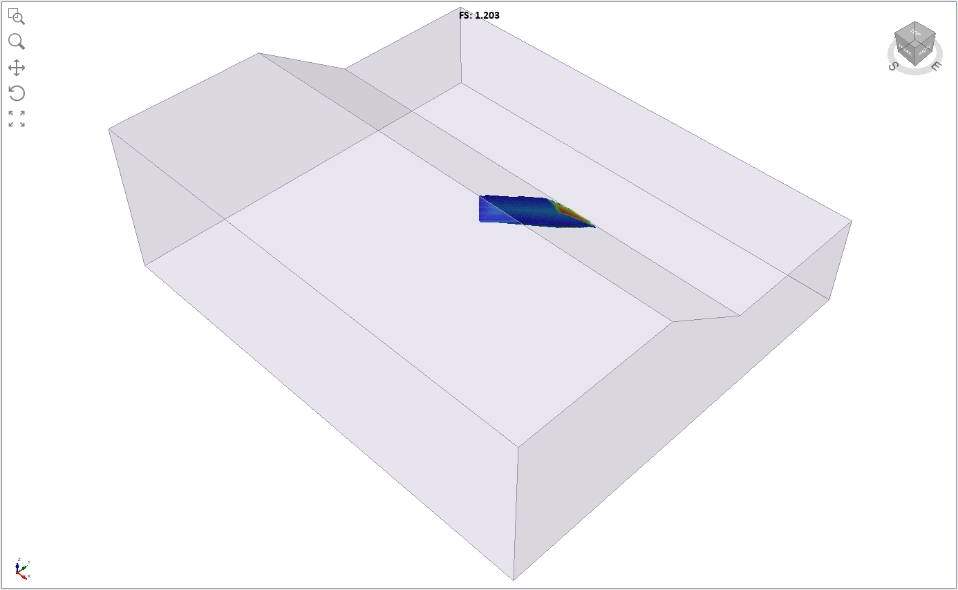
You can clearly see the shear strength of the two planes (blue contours) which intersect to form a wedge-like failure surface.
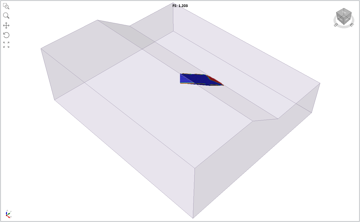
This clearly highlights the low friction angle (15 degrees) of the two weak planes (blue colour) in contrast to the higher strength of the failure surface at other orientations.
3.0 Two Planes of Different Strength
As an additional exercise, we will assign the stronger material to the second plane.
- Click on anisotropic material properties, and under the Generalized function dialog, select edit and assign the Stronger material to the second plane.
 In case if the geometry views are zoomed out, resume to zoom all view by pressing F2.
 - Save with a new file name and select Compute to re-run the analysis.
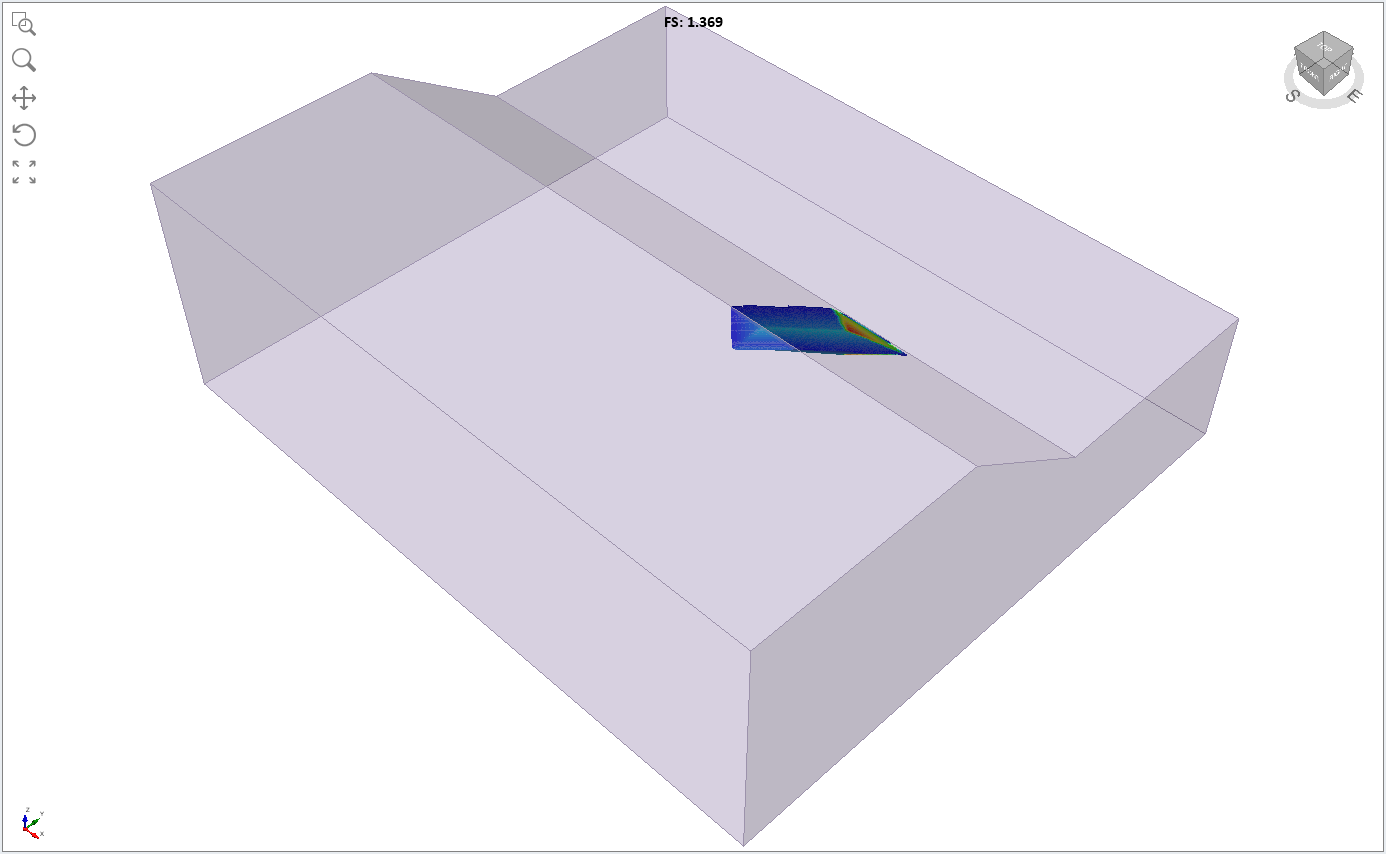
Notice that the critical slip surface is now slightly asymmetric, and the Bishop safety factor is slightly higher than the previous result, since we increased the strength of one of the anisotropic planes.
- Change the contour data to Shear Strength.
- Change the contour data to Base Friction Angle.
You can clearly see the different friction angle of the two anisotropic planes (blue = 15 degrees, light blue = 20 degrees).
This concludes the Slope with Two Anisotropic Planes tutorial.