Add Embankment (Cross Section)
Add Embankment (Cross-section) allows you to create an Embankment with user-defined coordinates in the cross-section view of the embankment. Once the cross-section shape is defined in the Cross-section Embankment dialog, you can place the embankment in 2D CAD view with a near/far point of the embankment. The advantage of this feature over the 'Add Embankment' is that it allows you to create any shape as long as the embankment shape does not overlap or cross itself. Similar to the Add Embankment feature, the embankments can have multiple layers with a user-defined staging sequence as well. Embankments are defined by a 2-dimensional cross-section, but represent 3-dimensional loads, because the embankments have a finite length, with user-defined end angles, and can be placed at any orientation with respect to other loads.
To add an embankment (cross-section) load:
- Select Loads > Load by Zones

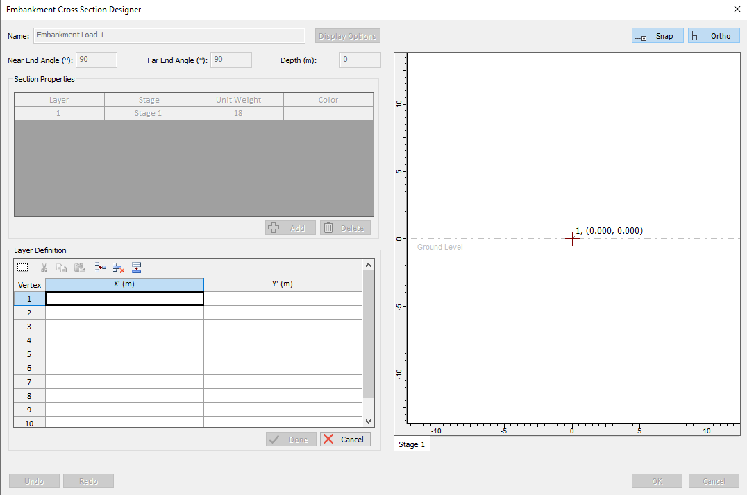
- You will see the Embankment Cross Section Designer dialog. This dialog allows you to define the 2-dimensional cross-section of the embankment with the CAD drawing tools on the right side of the dialog. To start:
- Select 'Add' button on the Section properties. This will prompt Initial Section Settings.
The following parameters are required for each layer of the embankment.
- Stage - the installation stage for the layer of the embankment.
- Unit Weight - the unit weight of the material of the layer of the embankment.
- Colour - the colour of the embankment shown in the CAD view.
You can then freely draw the cross-section shape of the embankment with coordinates in the layer definition or in the CAD View drawing pane.
- You can add more layers by selecting the 'Add' button on section properties, which will allow you to create another layer of embankment with different shape, unit weight, colors, and stage of the embankment.
- If the embankment is symmetric, then it does not matter in which order you enter the two points.
- If the embankment is NOT symmetric (e.g. left and right bench widths are different), then the order in which you enter the two points determines the apparent orientation of the embankment. See the note below.
Other Cross Section Embankment Designer inputs
In the Embankment Designer dialog, the following input parameters define the embankment cross-section properties.
- Name - This defines the name of the cross-section embankment. You can select the Display option to configure the text display on the embankment.
- Near-End / Far-End Angles - this defines the slope at each end of the embankment. If you are not concerned with modelling the ends of the embankment, then you can just leave the default values of 90 degrees (i.e. a vertical face at each end of the embankment)."Near" and "far" depend on the order in which you enter the two points which define the embankment centerline, in step 3 (see above). The "near" end of the embankment corresponds to the first point, and the "far" end corresponds to the second point.
- Elevation / Depth - this defines the bottom elevation/depth of the cross-section embankment applied to the model.
For more details on how to use this feature, please refer to our Tutorial 19 - Cross-section embankment designer.
Note about Infinite Embankments
You cannot explicitly model an embankment of infinite length in Settle3 (e.g. if you wish to simulate a 2-dimensional plane strain analysis). To simulate an embankment of "infinite" length in Settle3, simply define a length which is sufficient to avoid the 3-dimensional end effects of the embankment load, at the measurement point of interest.