Dynamic Compaction
Dynamic Compaction is a ground improvement method that involves dropping a heavy tamper in a grid pattern to densify loose soil particles.
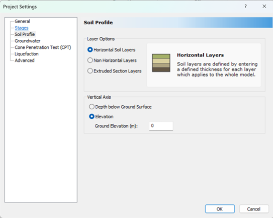
Dynamic compaction is only available when Horizontal Soil Layers is selected from the Project Settings dialog:
When dynamic compaction is selected as the ground improvement method, the following options will appear in the Ground Improvement Region dialog:
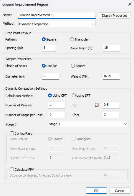
Drop Point Layout
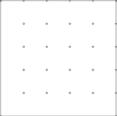
Define the grid for the primary pass by selecting one of two patterns:
- Square Pattern
- Triangular Pattern
The chosen pattern will affect the influence area () used when computing the applied energy per unit area.
| Pattern | Influence Area |
| Square | Ae = s2 |
| Triangular | Ae = 0.867 * s2 |
Where s is the drop spacing.
 |
 |
| Square Drop Pattern | Triangular Drop Pattern |
Tamper Properties
In addition to the weight of the tamper, the user will choose the geometry of the tamper’s base then specify its size:
- Circular: specify the diameter
- Square: specify the width
Dynamic Compaction Settings
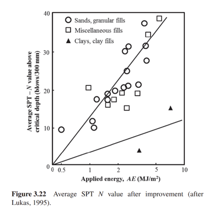
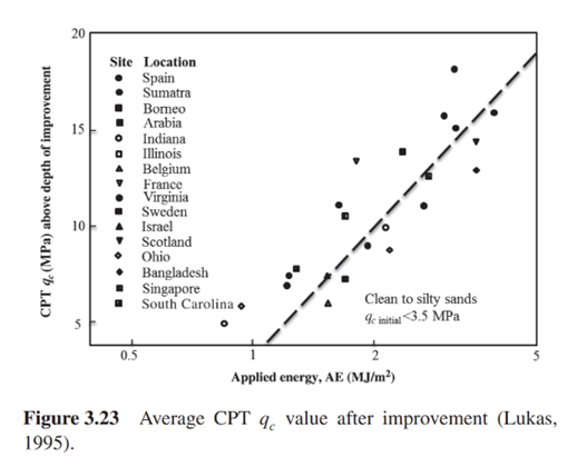
The Calculation Method radio buttons allow the user to select between correlating the applied energy from dynamic compaction to improved SPT-N and CPT qc values presented in Lukas 1995 (see below):
 |
 |
SPT – N after improvement |
CPT qc after improvement |
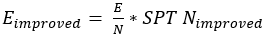
The improved modulus of elasticity is calculated by multiplying the correlation ratio by the improved SPT-N or CPT qc.
- For CPT:

- For SPT:
If the applied energy exceeds the bounds of the graphs shown above, the value of improved SPT-N or CPT qc will be capped by the maximum or minimum.
- Number of Passes: How many high-energy passes the tamper will make over the drop grid
- Number of Drops per Pass: The number of blows delivered at each drop point during a single pass
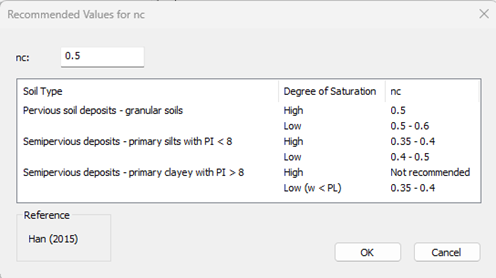
- nc : Empirical constant
Settle3 provides a table of recommended values of nc adopted from Han (2015). To access this table, click the  icon to open the input box:
The Bottom Depth of the ground improvement region is based on the depth of improvement, calculating from the following expression:
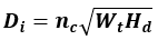
Where:
- nc = empirical constant (dependent on soil type)
- Wt = tamper weight
- Hd = drop height
- Di = depth of improvement
Settle3 automatically calculates Di from the dialog inputs and updates the 3D view to ensure the displayed region always reflects the energy-based calculation.
To further densify loose soil particles at the surface of the impact craters, engineers often opt to include a final lower energy ironing pass. To include an ironing pass in Settle3:
- Tick the Ironing Pass checkbox
- Enter the same tamper setting used for the high-energy pass: pattern, spacing, drop height tamper weight and number of drops
The additional applied energy contribution from the ironing pass will be added to the cumulative applied energy when estimating the post-improvement SPT-N or CPT qc.
Peak particle velocity (PPV) is an indicator of vibration-induced risk, representing the maximum instantaneous speed at which soil particles travel during a vibration event.
To calculate PPV:
- Tick the Calculate PPV checkbox.
- Specify the distance to the nearest affected structure.
The peak particle velocity will be calculated as follows:
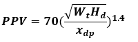
Where:
- PPV = Peak Particle Velocity (mm/s)
- Wt = tamper weight (ton)
- Hd = drop height (m)
- xdp= distance to drop point (m)
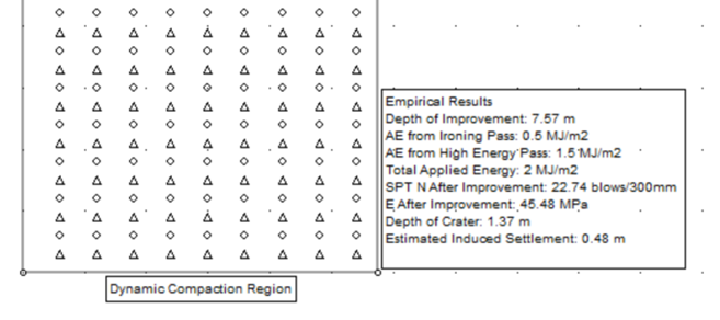
Results
After drawing the ground improvement region, the following list of empirical results will appear next to the ground improvement region:
- Depth of Improvement
- Applied Energy from Ironing Pass
- Applied Energy from High Energy Pass
- Total Applied Energy
- CPT qc or SPT N After Improvement
- Elastic Modulus After Improvement
- Depth of Crater
- Estimated Induced Settlement
- Peak Particle Velocity
For further details on the calculations of the output results, please refer to the example presented in the Settle3: Dynamic Compaction Verification Manual.
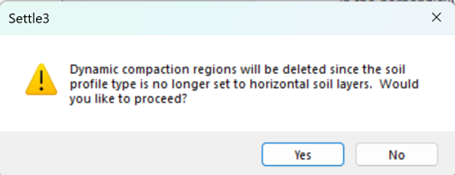
Switching the Layer Option from Horizontal Layers to Non-Horizontal or Extruded Section Layers in the Project Settings will result in a warning appearing. Clicking Yes will remove all the Dynamic Compaction regions from the model.