Definition of the Surface
The Fragmenter requires the generation of a dedicated surface for the fragmentation analysis. The generation of the surface is defined by the camera view vertically downwards (“Generate Top Down”) or from a user defined view, which is currently visible in the 3D viewer (“Generate from View”). In addition, the surface to analyse can be limited by defining a so called Region of Interest (ROI).
- Open a 3D model by clicking “File | Open 3D Model” in the menu bar and the dialog “Open 3D model” occurs and inspect the 3D model in the viewer.
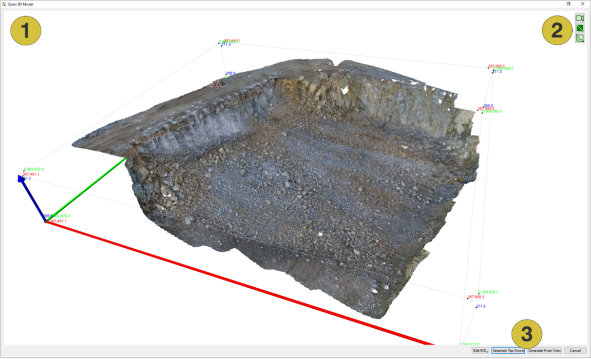
- 3D viewer
- View options
- Features
- Optional – limit the generation of the surface to certain area by defining a region of interest (ROI). See description below.
- Generate the surface by using one of the following options:
- Top Down: Click the “Generate Top Down” button to generate the surface for fragmentation analysis from the camera view (top down). This will be sufficient for most of the muck piles in quarry operations surveyed by aerial imagery with Nadir flights.
- From View: Align the 3D model in the 3D viewer such that you have an optimized view on the fragments. Click the “Generate From View” button to generate the surface for fragmentation analysis from the current view. This will be the preferred method if the muck pile has a significant slope and it was surveyed towards this particular direction (e.g. from the ground or with inclined cameras).
Region of Interest (optional)
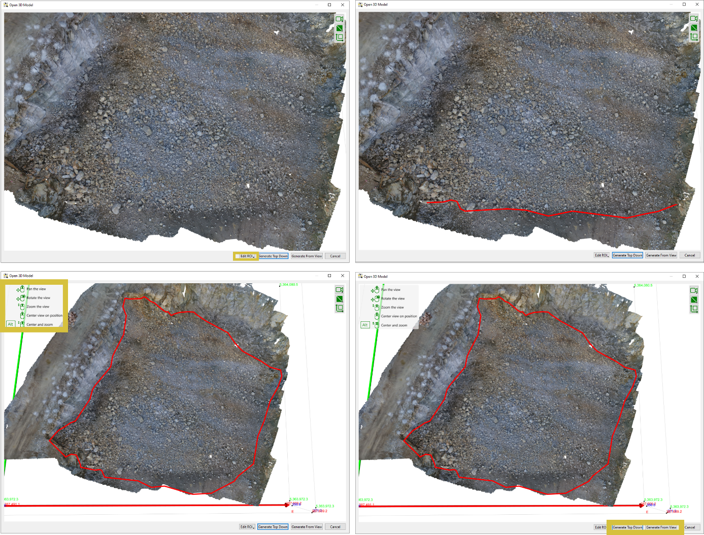
Limit the generation of the surface to a specific area as follows (see below):
- Click the “Edit ROI” button and select “Edit ROI” in the pull-down menu
- Mark the border line of the Region of Interest on the 3D model by clicking the left mouse button. A polygonal line grows instantaneously.
- Confirm the polygon by pressing the “Enter” key or the middle mouse button
- Edit the ROI by using the commands for “Add Point”, ”Insert Point”, “Delete Point”, “Move Point” and “Delete Last Point”. See keyboard tooltips by pressing F1.
- Delete the ROI by choosing “Delete ROI” from the pull-down menu
The ROI is used for trimming a 3D model. To confine the fragmentation analysis to a specific region use the analysis mask (see Run Fragmentation Analysis topic).