Edit Spot Bolts
Moving Spot Bolts
Once a Spot Bolt is added with the Add Spot Bolt option, you can then move and orient the Spot Bolt in 3D with the Move Spot Bolt option, as follows:
- Select the 3D Wedge View
 .
. - Select Move Spot Bolts from the View menu. Or, alternatively, you can right-click the mouse directly on a Spot Bolt, and select Move Spot Bolts from the popup menu.
- All Spot Bolts on the model will then be highlighted by "handles" at the start and end points of each Spot Bolt. These handles appear as a red cube at the start point, and a blue cube at the end point of each bolt.
- If you hover the mouse over either of these handles, the cursor will change to a 4-way arrow symbol. When you see this symbol, you can click and drag the ends of the Spot Bolt to any location on the model.The start point of a Spot Bolt (the "red cube"), can only be moved along the surface of the Opening Section boundary. When the start point is moved, the entire bolt will be translated (i.e., the length and orientation of the bolt will not change, only the installation point on the surface of the excavation will change). The endpoint of a Spot Bolt (the "blue cube") can be moved to any 3-dimensional location in the view, to change the orientation and/or length of the bolt.
- When you move the ends of a Spot Bolt, you will see that the length, orientation and coordinates of the bolt are displayed in the views. The movement of Spot Bolts in this manner is very similar to the use of the Length and Angles measurement option in UnWedge. For more information you can see the Length and Angles topic.
TIP: In the 3D Wedge View, you can move Spot Bolts in any of the four views: Perspective, Top, Front or Side views. However, for practical purposes, you may find it most convenient to move the Spot Bolt within the three orthogonal views (Top, Front, Side) to get the desired placement of the bolt. The exact placement of a Spot Bolt in the Perspective view can be difficult. You are encouraged to experiment with this option.
Editing Spot Bolts
The Edit Spot Bolt option allows you to change the length of a bolt, assign a different bolt property type to the bolt, and more precisely move the installation point of the bolt.
To edit Spot Bolts:
- If you are viewing the Perimeter Support Designer
 view, you can select Edit Spot Bolt
  from the Edit sub-menu of the Support menu. You must then select a Spot Bolt (click on a bolt with the mouse), then right-click and select Done
  from the popup menu, or press ENTER. You will see the Edit Spot Bolt dialog.
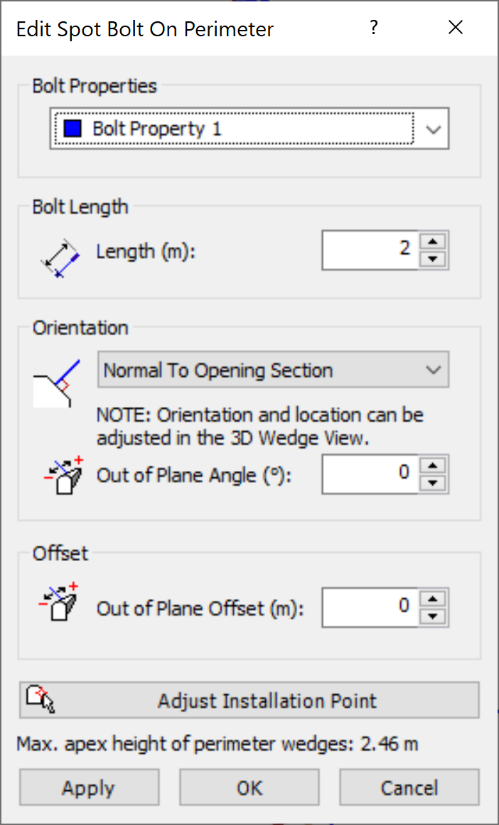
Edit Spot Bolt on Perimeter dialog - Alternatively, a more convenient right-click shortcut is available; right-click directly on a Spot Bolt, and select Edit Spot Bolt from the popup menu. The right-click shortcut is available on 2D views (Perimeter Support Designer view) as well as 3D views (3D Wedge View).
- In the Edit Spot Bolt dialog, you can change the Bolt Properties type, Bolt Length, or Out of Plane Offset.
- Select Apply to apply the changes without closing the dialog or select OK.
Adjust Installation Point
You can also edit the installation points of the pattern, from the Edit Spot Bolt On Perimeter dialog, as follows:
- Select the Adjust Installation Point button in the dialog.
- The dialog will close, and you will be prompted to select an installation point of the bolt. This is the start point of the bolt on the excavation. The installation point will be highlighted by a cross-hair icon.
- Hover the mouse over an installation point, and the cursor will change to a 4-way arrow symbol.
- When you see this, you can click and drag the point to a new location.
- As you move the installation point, the spot bolt will be interactively updated on the screen.
- When the installation points are moved to the desired locations, right-click and select Done , or press ENTER, and the updated pattern will be applied to the model.