Add Shotcrete Layer
Shotcrete can be applied to the perimeter of the excavation, with the Add Shotcrete Layer option (Perimeter Support view).
To apply a layer of shotcrete to the perimeter:
- First, make sure you are viewing the Perimeter Support Designer view (select the Perimeter Support Designer
 button from the toolbar).
 - Select the Add Shotcrete Layer On Perimeter
 option from the Sidebar, the Support menu or the right-click menu.
 - You will see the Add Shotcrete Layer On Perimeter dialog.
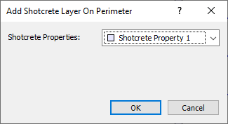
Add Shotcrete Layer on Perimeter Dialog
This allows you to select the shotcrete property type for the layer you are going to add. - Select the Shotcrete Properties from the drop-list, and select OK.Shotcrete properties are created and defined with the Shotcrete Properties option.
- You will then be prompted to enter the starting and ending points for the shotcrete layer on the perimeter. This can be done graphically with the mouse, or by entering coordinates in the prompt line.
- Start Point: You will notice a cross-hair icon which appears on the Opening Section boundary, and follows the mouse movement. You can use this cross-hair to graphically locate the starting point of the layer on the perimeter. If the Snap option is toggled, the cross-hair will snap exactly to vertices. Snap can be toggled in the right-click. Click the left mouse button when the cross-hair is at the desired location. Alternatively, you can type in the coordinates of the start point in the prompt line.
- End Point: As you move the mouse, the shotcrete layer will be drawn on the model, in a counter-clockwise direction from the Start point. The shotcrete layer will appear as a thin strip drawn inside the perimeter. Use the cross-hair cursor to graphically locate the endpoint, or type the coordinates in the prompt line.
Multiple Shotcrete Layers
On the perimeter, you are not restricted to only a single shotcrete layer. You may define any number of layers as required, by repeating the above steps. Multiple shotcrete layers can be located anywhere on the perimeter, and the layers are allowed to overlap in any manner. Each layer can have different properties.
Display of Shotcrete Layer
Shotcrete is displayed in the Perimeter Support Design View, as a thin strip drawn inside the perimeter. The colour of a shotcrete layer is the colour of the shotcrete property type you have assigned to the layer.
The shotcrete layer thickness as displayed does NOT represent the actual thickness of the layer (as defined in Shotcrete Properties). The shotcrete layer thickness (as displayed on the 2d view) is always constant, relative to the dimensions of the Opening Section. If multiple layers are added, all layers are displayed with the same thickness, regardless of the actual thickness of the layers.
On the 3D views (3D Wedge View, Multi-Perspective View), shotcrete is displayed on the 3-dimensional excavation by shading the surface of the excavation with the colour of the shotcrete, where the shotcrete has been applied. If multiple layers of shotcrete have been applied, and the layers overlap, the shading which you see in the 3D views, will represent the final layer(s) of shotcrete, as would be visible from within the excavation.