Add Bolt Pattern
A regular pattern of bolts can be applied to the perimeter of the excavation, with the Add Bolt Pattern (Perimeter Support) option. The pattern location, bolt length, spacing, orientation, z-offset, can all be defined by the user.
To apply a pattern of bolts to the perimeter:
- First, make sure you are viewing the Perimeter Support Designer view (select the Perimeter Support Designer
 button from the toolbar).
 - Select the Add Bolt Pattern
 option from the Sidebar, the Support menu or the right-click menu.
 - You will see the Add Bolt Pattern On Perimeter dialog.
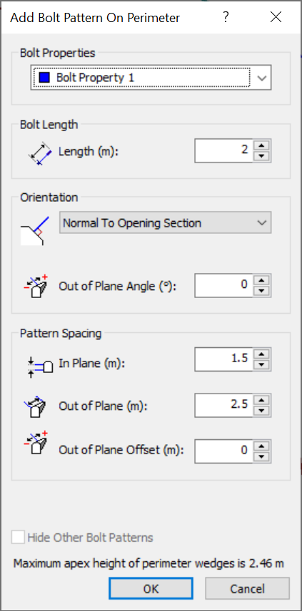
Add Bolt Pattern on Perimeter dialog - In the Add Bolt Pattern On Perimeter dialog, enter the following information and select OK.
- You will then be prompted to enter the drilling point (if applicable, see below), and the starting and ending points for the pattern.
- Drilling Point: If you selected Orientation = From Drilling Point, you will first be prompted to enter the x-y coordinates of the origin of a radial drilling pattern. You can enter the point graphically with the mouse, or you can type the coordinates in the prompt line. (For other pattern orientations, you will not see this prompt, proceed directly to Step 6).
- Start/End Points of Pattern: For all Orientation types, you must define the starting and ending points of the pattern, on the perimeter of the excavation (i.e., on the Opening Section boundary). This can be done graphically with the mouse, or by entering coordinates in the prompt line.
- Start Point: You will notice a cross-hair icon which appears on the Opening Section boundary, and follows the mouse movement. You can use this cross-hair to graphically locate the starting point of the pattern on the perimeter. If the Snap option is toggled, the cross-hair will snap exactly to vertices. Snap can be toggled in the right-click. Click the left mouse button when the cross-hair is at the desired location. Alternatively, you can type in the coordinates of the start point in the prompt line.
- End Point: As you move the mouse, the Bolt Pattern will be drawn on the model, in a counter-clockwise direction from the Start point. The bolts will be oriented according to the type of Pattern Orientation you have selected. Use the cross-hair cursor to graphically locate the endpoint, or type the coordinates in the prompt line.
- When the End Point has been entered, the pattern will be added to the model.
Bolt Properties
Assign the desired bolt property to the pattern. This will apply to all bolts in the pattern. Bolt properties are created and defined with the Bolt Properties option.
Bolt Geometry and Pattern Placement
Bolt Length
The length of all bolts in the pattern. Note that the Maximum Apex Height of all Perimeter Wedges is listed in the dialog. You can use this as a guide for setting the bolt length.
Orientation
The orientation of the Bolt Pattern which can be defined as one of the following:
- Normal to Opening Section- all bolts will be normal (perpendicular) to the Opening Section boundary.
- Local Trend and Plunge - this allows you to define the trend and plunge of the bolts in the pattern relative to the tunnel axis direction (i.e., the tunnel axis acts as the local azimuth).
- Angle to Local X Axis - this allows you to specify that all bolts in the pattern are installed at the same angle. The angle is specified relative to the local X (horizontal) axis of the Opening Section.
- From Drilling Point - with this option, a drilling point must be specified. This will define the origin of a radial drilling pattern for the bolts.
By default, all bolts that are part of a Bolt Pattern will lie in the x-y plane (with the exception of Local Trend and Plunge orientation) and thus will be orthogonal to the extrusion z-direction. Both end points of the bolt will have the same z-coordinate. To angle the bolts out of plane (z-direction), the Out of Plane Angle option is used. The angle is measured in a plane containing both the bolt and the z-axis. The angle is measured from the bolt in the x-y plane (angle = 0).
Spacing
The In Plane Spacing is the distance between each bolt in the pattern, measured along the perimeter of the boundary, in the plane of the Opening Section.
The Out of Plane Spacing is the distance between each row of bolts in the pattern, measured along the axis of the excavation.
Out of Plane Offset
By default, a bolt pattern is positioned along the z-axis of the excavation, such that the pattern is aligned with the z = 0 coordinate. In UnWedge, z = 0 is the plane parallel to the Opening Section, which contains the apex of each perimeter wedge as drawn on the 3D Wedge View.
If you want to shift the position of the Bolt Pattern along the axis of the excavation, then enter a value for the Out of Plane Offset. The value of the Out of Plane Offset should be less than the value of the Out of Plane Spacing.
The Out of Plane Offset option is useful if you wish to test the sensitivity of the Factor of Safety to the z-location of the pattern along the tunnel (e.g. run the analysis with zero offset, and then re-run it with the offset = half of the Out of Plane Spacing).
The Out of Plane Offset option is also useful for offsetting the z-positioning of multiple Bolt Patterns (e.g. place a second pattern halfway between rows of the first pattern).
Notes:
- The pattern will always begin exactly at the Start point you have entered.
- The distance between each bolt along the perimeter is determined by the In Plane Spacing you entered in the Add Bolt Pattern On Perimeter dialog. Remember that the In Plane Spacing is always measured along the line segments of the perimeter.
- The pattern will not necessarily end exactly at the End point you have entered, unless the distance along the perimeter between the Start and the End points is an exact multiple of the In Plane Spacing.
- If you are not happy with the pattern, you can Delete
 the pattern, Edit
  the pattern, or select Undo
 .
.
Multiple Bolt Patterns
On the perimeter, you are not restricted to only a single Bolt Pattern. You may define additional Bolt Patterns as required, by repeating the above steps.
Multiple Bolt Patterns allow you to define patterns with different bolt properties, lengths, spacings, etc. The Out of Plane Offset option (see above) allows you to offset different patterns by a specified amount, in the direction of the tunnel axis.