Multi-Section Creator
The RocFall2 Multi-Section Creator allows users to create multiple 2D sections from any 3D model. Sections can be created one at a time or as a batch in the multi-section creator. Sections can then be exported to RocFall2. If exported together in a group, group analysis for the batch section can be conducted in RocFall2.
In order to use the multi-section creator, make sure you have an existing model or geometry present. If not, import the model by selecting File > Import > Import Geometry
 and open the file containing the model.
Once you have a model loaded:
-
Select Geometry > RocFall2 Section Creator
 or select the RocFall2 Section Creator
icon from the toolbar.
or select the RocFall2 Section Creator
icon from the toolbar.
- Once the Create/Edit Section dialog opens, select the Create Multiple Sections button to start defining multiple 2D sections in a batch. If you already have sections defined in the model, you can access the Batch Section Creator by selecting Create Multiple Sections
 located at the bottom-left hand corner of the dialog
 - In the Batch Section Creator dialog, there are two options to create the sections:
- Sections per Segment
- As Drawn
- Sections per Segment
In both cases, you will need to draw a polyline in the model preview in order to define the 2D sections. To draw a polyline, select the Draw button located at top of the table.
You will see the model preview update to only show the top-down view of the model. To draw the polyline, left-click where you would like to define the points. The polyline is shown in pink. Once you are content with your polyline, right-click and select Done.
Depending on which option was selected in the Creation Method, the drawn polyline will be used differently for the creation of the 2D sections, as described below.
Sections per Segment
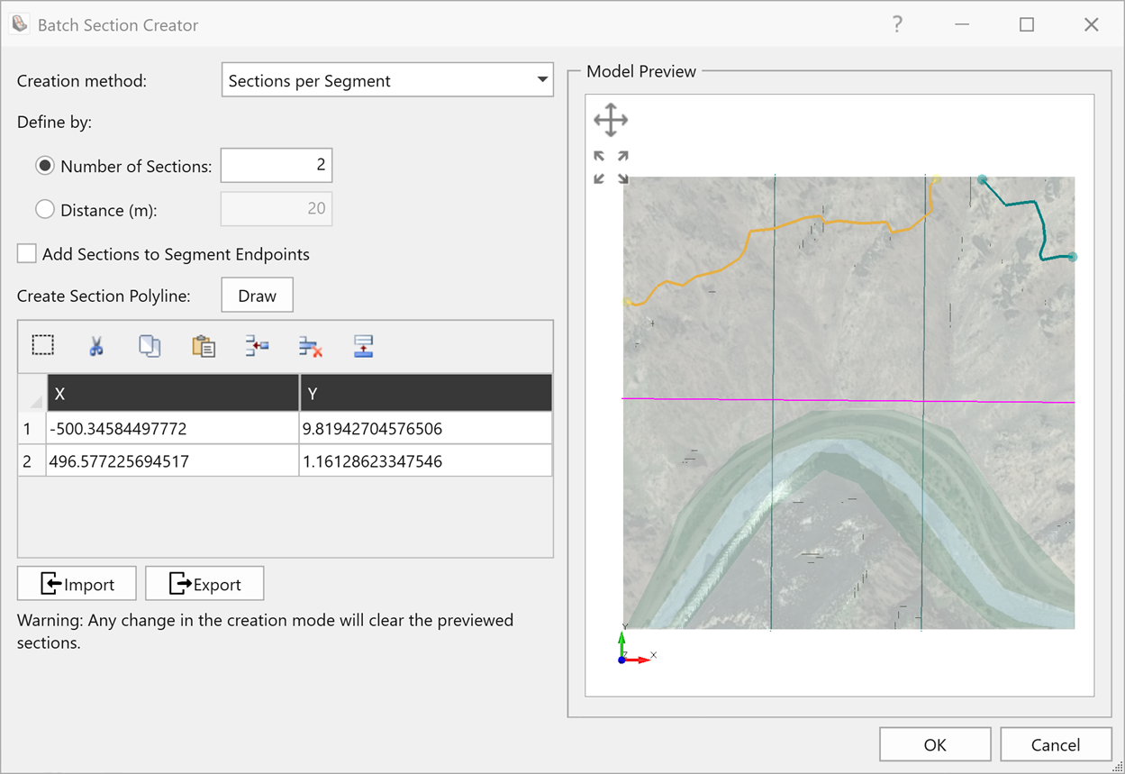
When this option is selected, sections are created perpendicular to the drawn polyline. The user can choose to define a Number of Sections that intersects each polyline segment or to specify a Distance between evenly spaced sections. .
Number of Sections
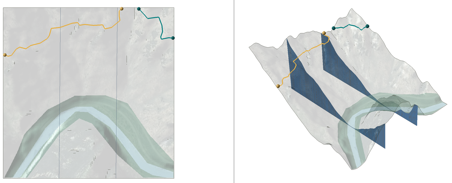
This is the number of sections that will be created at equal spacing across each polyline segment. For example, as shown by the image below, we have set the Number of Sections to 2. This will divide the pink polyline segment into 3 equal segments, resulting in 2 sections as shown in green.
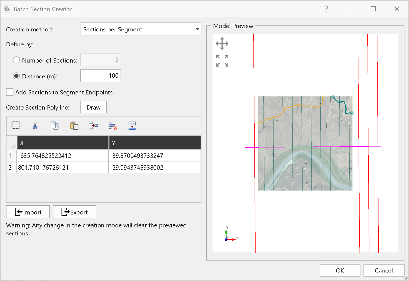
Distance
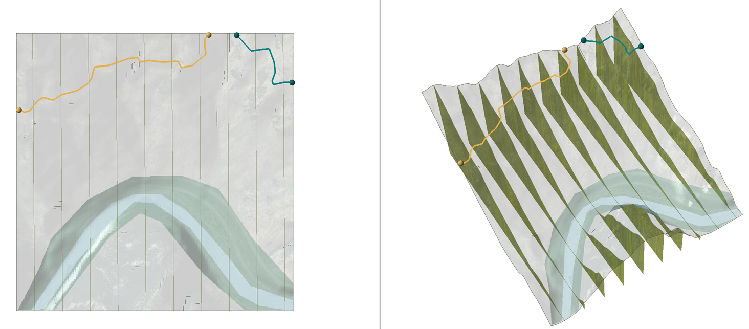
Multiple 2D sections are created at this specified Distance across the polyline. For example, if we define the Distance as 100 m, the program will create a 2D sectionat every 100 m along the length of the polyline. The same example as above but with a distance of 100 m results in the following 2D sections:
Add Sections to Segment Endpoints
If this option is enabled, a 2D section will be added to the endpoints of each polyline segment.
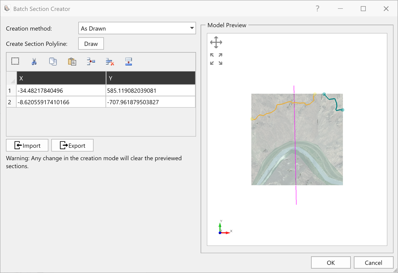
As Drawn
When this option is selected, the 2D section is defined by the drawn polyline itself
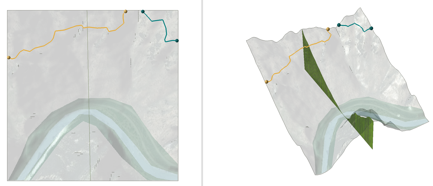
The simplest way to use this option is to draw a polyline across the model using only two endpoints, as illustrated below.
Alternatively, you can draw a polyline with several different segments, as shown below.
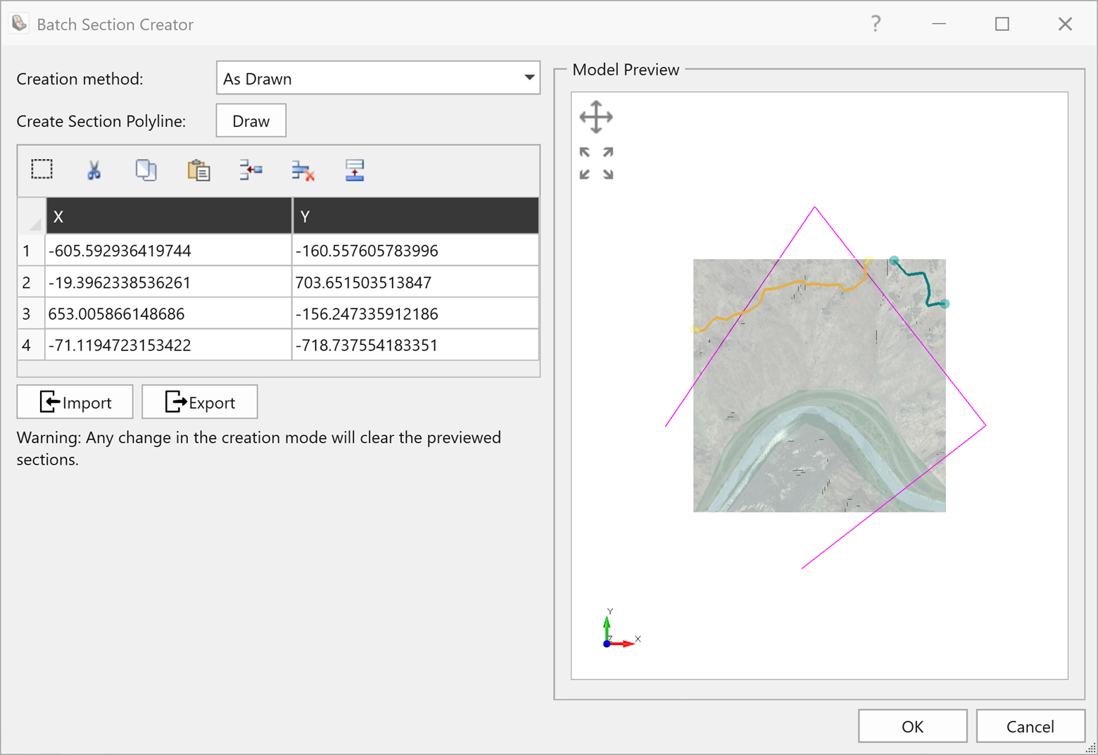
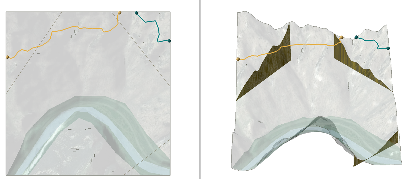
In this case, the program will create a 2D section for each drawn segment. See below for the sections created by the above polyline definition.
For more details on the RocFall2 Section Creator, please see our Section Creator tutorial.