Add Bolts to Selected Surface
The Add Bolts to Selected Surface option is used to add bolts to a model. Bolts can be added
as individual spot bolts or bolt patterns to External Volume geometry.
To add bolts:
- Navigate to the Loading & Support workflow tab
- Click the desired surface in the 3D View to select it.
- Select: Support > Add Bolts to Selected Surface

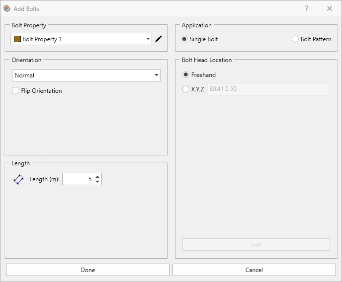
- You will see the Add Bolts dialog. Select the Bolt Property. See the Define Bolt Properties topic for more information about bolt properties.
- Select the Orientation of the bolt(s).
- Normal: bolts are applied normal to the boundaries
- Trend/Plunge: specify a trend and plunge
- Vector (x,y,z): specify x,y,z vector components
- While adding bolts, the orientation may sometimes be opposite from the intended direction (i.e. 180 degrees off). If this occurs you can select the Flip Orientation checkbox.
- Set the Length of the bolt(s), as measured along the axis of the bolt.
- The Application can be either:
- Single Bolt
- Bolt Pattern
Single Bolt Application
- Select the Application = Single Bolt to add individual bolts to the model. You can add one or more single bolts without closing the dialog, and the bolts may have different properties, orientation or location.
- Select the method to use in specifying the Bolt Head Location:
- Freehand: add bolts by clicking the mouse at the desired bolt head location on the selected face.
- X, Y, Z: enter coordinates of the bolt head location on the selected
face.
The Bolt Head Location must be on the selected geometry (i.e., face or edge).
- When all bolts have been added to the selected face, click OK to complete and close the dialog.
Bolt Pattern Application
- Select Application = Bolt Pattern to add a bolt pattern to the model. You can add one or more bolt patterns without closing the dialog, and the patterns may have different properties or orientation.
- The Bolt Pattern options allow you to define a region (on the selected face) on which a pattern
of bolts will be added. This region is defined by the Primary Path and a Secondary Path. The start points
selected for both the primary and secondary paths should be the same.
- Primary Path: this is the primary direction of the bolt pattern. It is defined by entering Start and End points graphically with the mouse or by entering coordinates in the edit boxes. The start and end points of the primary path determine the range in which bolts of the bolt pattern will be added in the primary direction.
- Secondary Path: this is the secondary direction of the bolt pattern. By default, if this checkbox is not selected, the Secondary Path will be perpendicular to the Primary Path. If you select the Secondary Path checkbox, then you can define Start and End points for the secondary path, which determines the range in which bolts of the bolt pattern will be added in the secondary direction.
- Primary Spacing: the spacing between each bolt of the pattern in the primary direction.
- Secondary Spacing: the spacing between each bolt of the pattern in the secondary direction.
- Primary Rows: the number of rows of bolts in the primary direction. The actual number will be equal to or less than this number.
- Secondary Rows: the number of rows of bolts in the secondary direction. The actual number will be equal to or less than this number.
- Primary Offset: allows you to define a starting location for the pattern in the primary direction, as measured from the starting point of the Primary Path.
- Secondary Offset: allows you to define a starting location for the pattern in the secondary direction, as measured from the starting point of the Secondary Path.
- When all of the parameters for the bolt pattern have been entered, select the Preview Pattern button. Each bolt of the pattern is represented as a square on the surface of the selected face. If the Preview appears incorrect, then adjust the bolt pattern parameters as required.
- If the pattern appears as desired, click the Add
 button to add the bolt pattern to the model.
- When all bolts have been added to the selected face, click OK to close the dialog.