20 - Soil Profile Modelling
1.0 Introduction
The Soil Profile option allows you to define a master profile of your geological or soil profile, over which you can superimpose an external boundary to create different slope geometries (e.g., cut back a slope).
Why Use a Soil Profile?
The Soil Profile option is useful when defining models with relatively complex material layering, over which you would like to define several different slope excavation scenarios. For example, it is useful for modelling an open pit mine with several material layers, which is to be excavated or cut back in stages. In this case, the profile boundaries will remain constant, while different external boundaries can be used to “cut” a slope out of the profile.
Soil Profile & Multi-Scenario Modelling
The Soil Profile option is most useful when used in conjunction with Multi Scenario modelling. When you use Soil Profile + Multi Scenario modelling, this creates a three-level modelling hierarchy as follows:
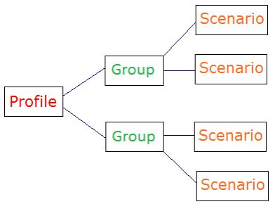
- The Soil Profile is constant for ALL groups/scenarios. If the Profile is edited, the changes will propagate to all scenarios in all groups.
- The External boundary is constant for EACH group but can vary between groups. If the external boundary is edited, it will propagate to all scenarios within that group.
- All other input can be modified individually for EACH scenario.
In this tutorial, we will learn how to:
- Define a soil profile in Slide2 and superimpose an external slope boundary on it.
- Create a soil profile from borehole measurements.
Finished Product:
The finished product of this tutorial can be found in the Tutorial 20 Soil Profile Modelling.slmd data file. All tutorial files installed with Slide2 can be accessed by selecting File > Recent Folders > Tutorials Folder from the Slide2 main menu.
2.0 Soil Profile Boundaries
To enable the Soil Profile:
- Select Analysis > Project Settings
 from the menu to open the dialog.
 - Select the Soil Profile tab.
- Tick the Use Soil Profile checkbox as shown below.
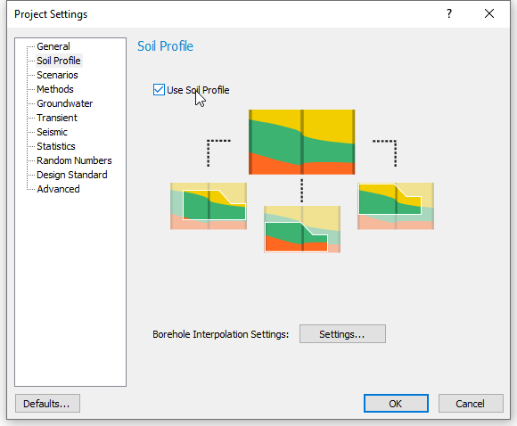
- Click OK to close the dialog.
The Profile option (with the soil profile modelling features) is now available as a workflow tab.
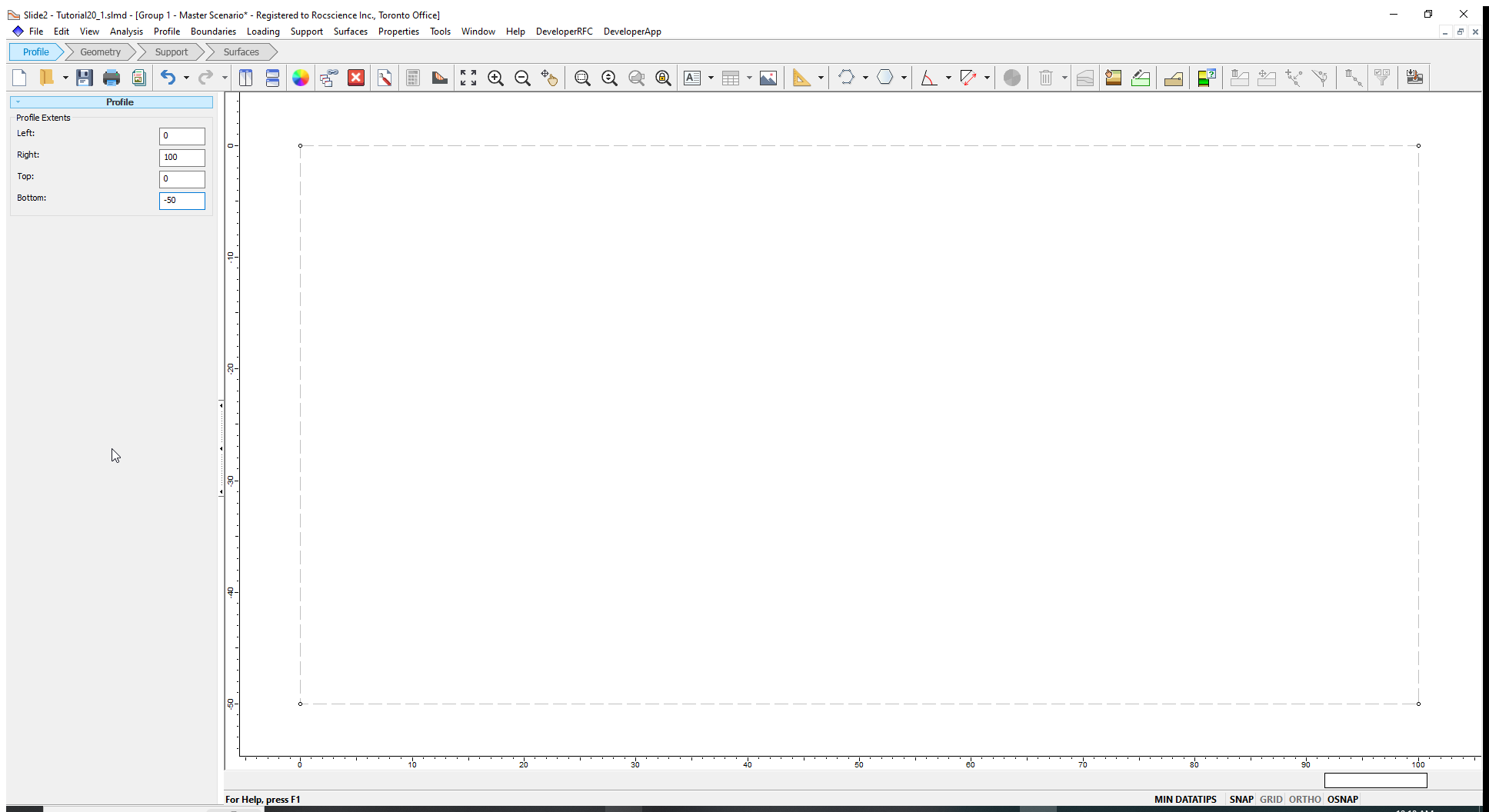
A Profile Extents input option is also provided in the sidebar on the left side of the screen. Here we will define the rectangular region (limits) of the soil profile boundaries.
- Enter the following values in the respective fields of the Profile Extents:
Left |
0 |
Right |
100 |
Top |
0 |
Bottom |
-50 |
The limits entered are now defined in the modelling window.
The next step is to define the Profile Boundaries. Profile boundaries can represent material boundaries, the ground surface, or other boundaries.
- Select Boundaries > Add Soil Profile Boundary
 from the menu.
 - Enter (0, -40) as the first coordinate in the Prompt line and press Enter. Enter (100, -30) as the second coordinate for the boundary and press Enter. Press Enter again to finish drawing the first boundary.
- Repeat steps (1) and (2) for the rest of the boundaries below.
- (0, -30) and (100, -20)
- (0, -20) and (100, -10)
- (0, -10) and (100, 0)
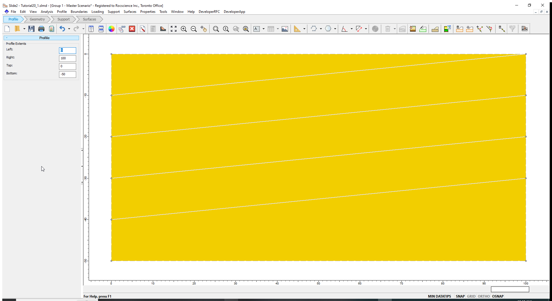
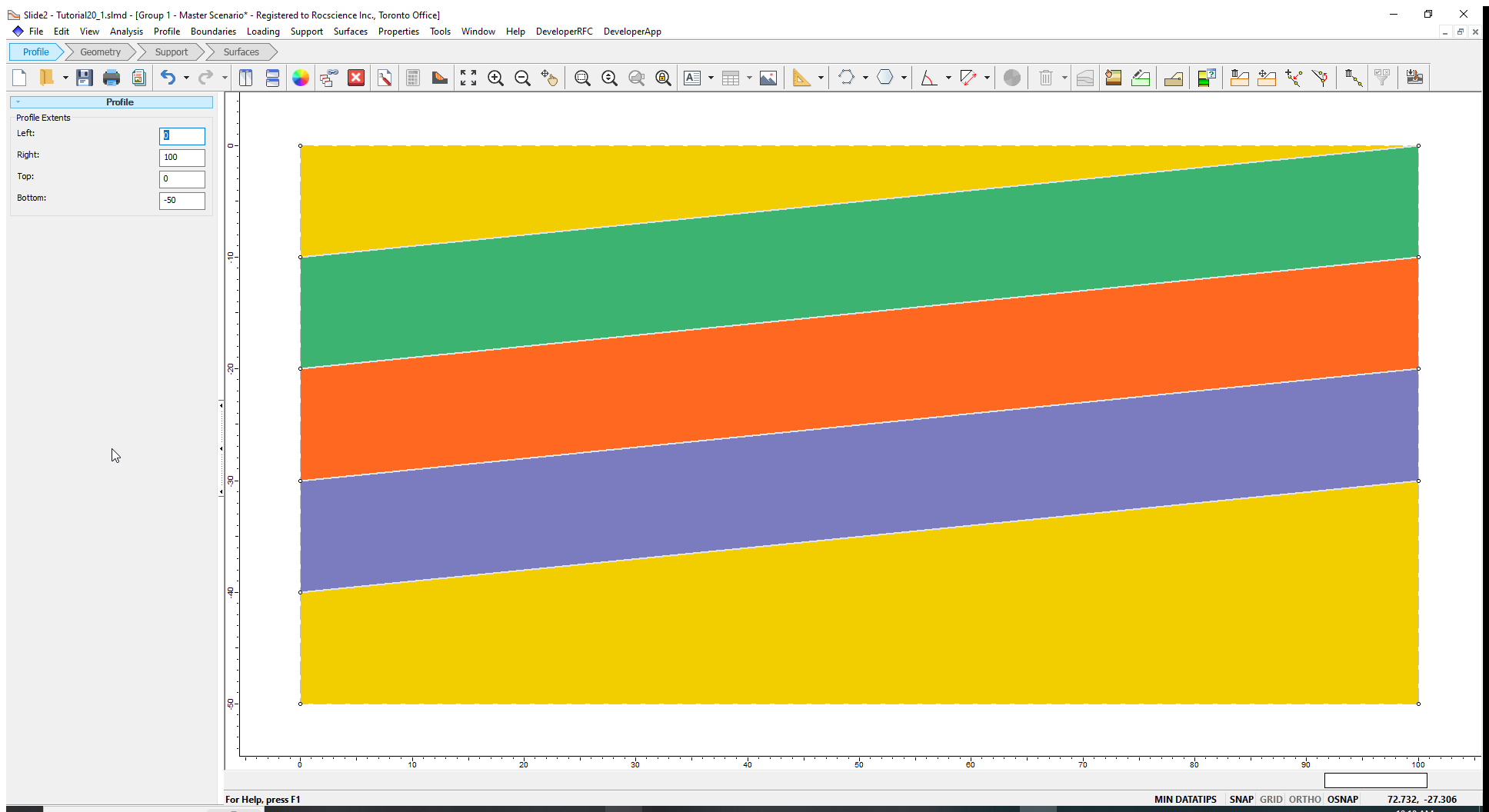
The soil profile boundaries are shown below:
We will now assign different materials to the regions.
- Right-click the mouse between the first and second profile boundaries (from the top) and select Assign Material > Material 2 from the popup menu.
- Right-click the mouse between the second and third profile boundaries (from the top) and select Assign Material > Material 3 from the popup menu.
- Right-click the mouse between the third and fourth profile boundaries (from the top) and select Assign Material > Material 4 from the popup menu.
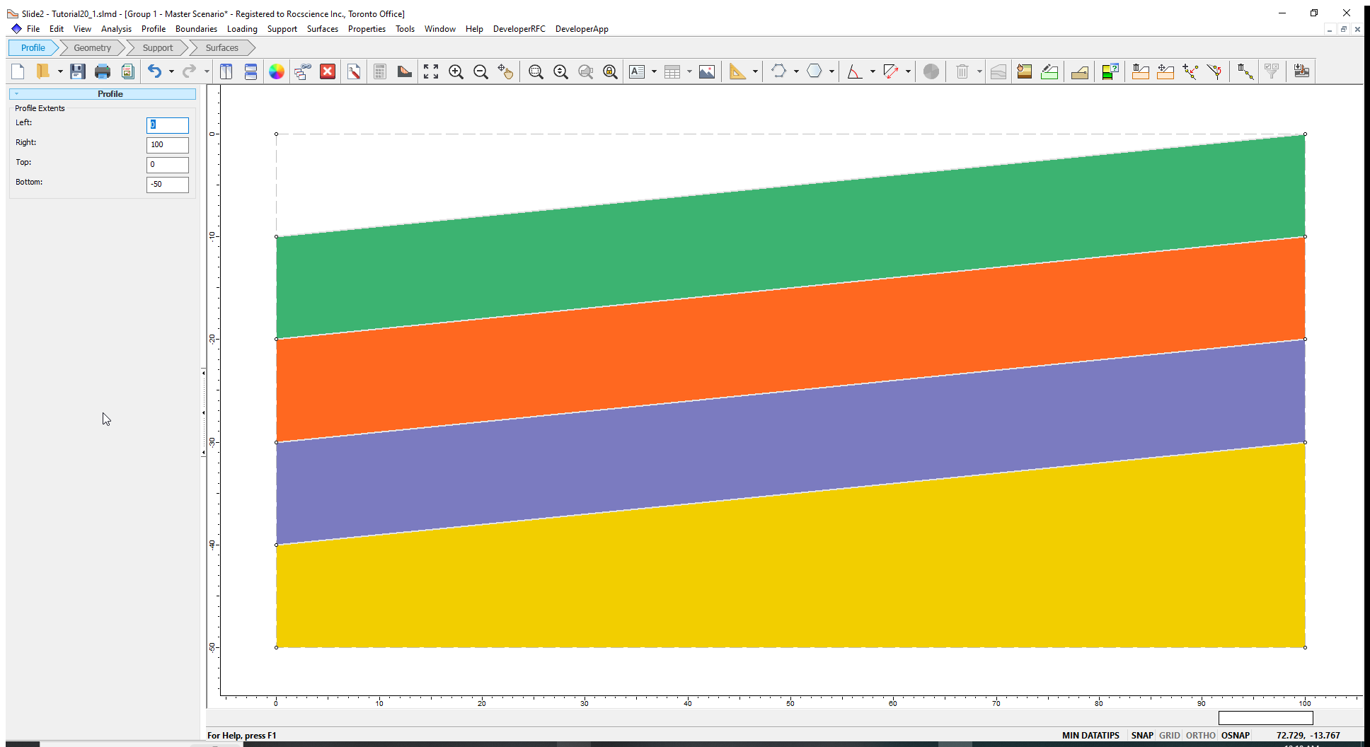
Your model should look as follows:
The next step is to define a ground surface for the soil profile. To do so, we will excavate the region at the top of the profile (area above region 2).
- Right-click the mouse on the top left region of the profile and select Assign Material > Excavate from the popup menu.
The top of the profile is now excavated.
The next step is to define the geometry of the slope. The external boundary should be within (or overlap with) the Profile boundaries/extents and not extend beyond the Profile Extents.
2.1 Slope External Boundary
- Click on the Geometry workflow tab. When the Geometry tab is selected, the Profile Boundaries and materials are displayed in a semi-transparent shade to indicate that you are no longer in the Profile mode.
- Select Boundaries > Add External Boundary

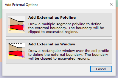
There are two options for adding an External Boundary with the Soil Profile feature:
- The external boundary can be entered as a user-defined polyline.
- The external boundary can be initially defined with a rectangular window, which is then used to "clip" the desired region of the profile, and the external boundary will be automatically generated from the clipped region.
- We will use the first method. Select the Add External as Polyline option.
- Enter the following coordinates for the External Boundary in the Prompt line:
(0, -50), (100, -50), (100, -5), (60, -5), (35, -20), (0, -20). - Press Enter.
- Go to View > Display Options. Uncheck the Profile checkbox to hide the profile boundaries.
The slope will look as shown below. The External Boundary has “cropped” the Soil Profile boundaries.
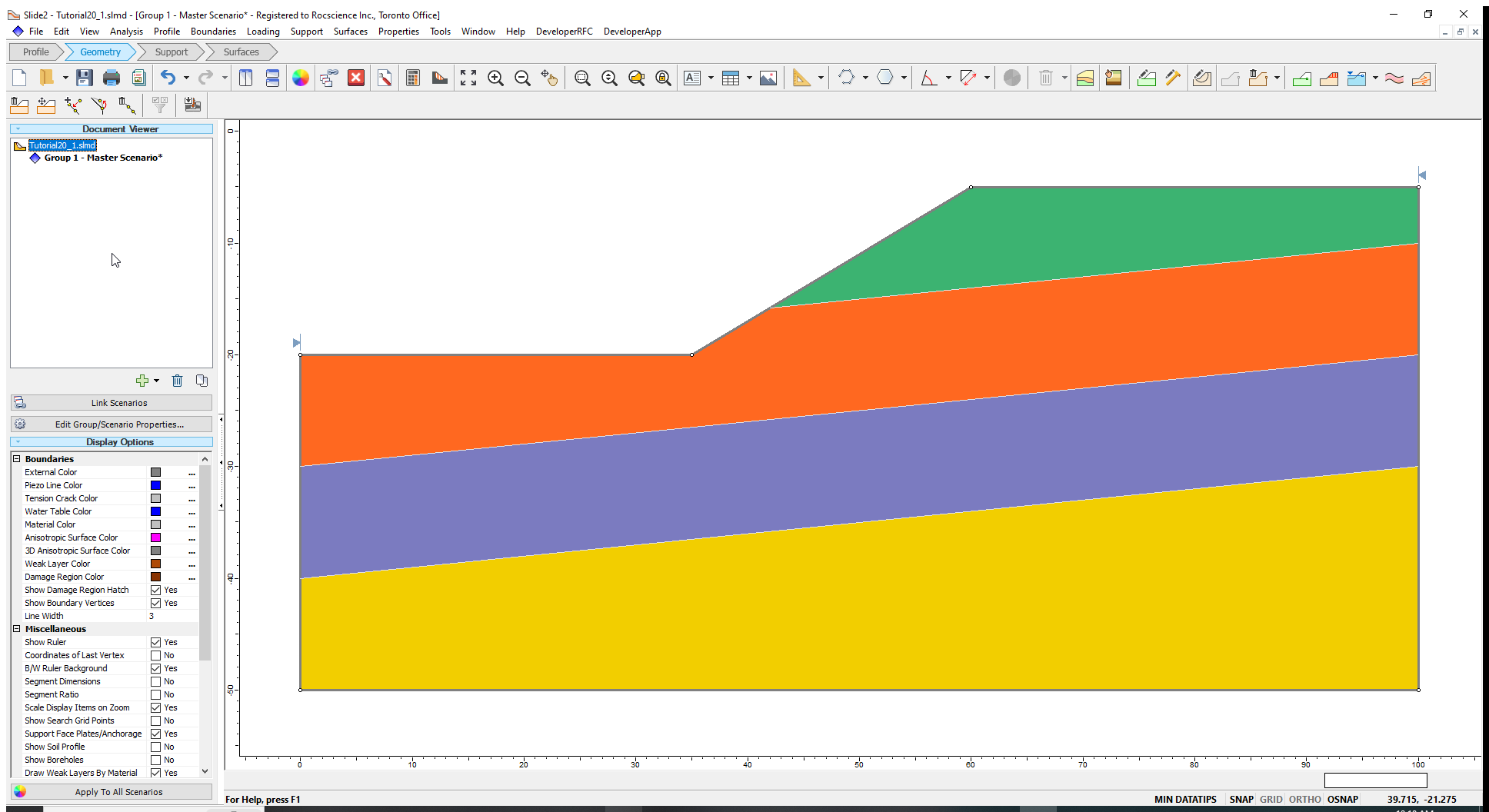
At this point you would set up your analysis by defining material properties, selecting your search criteria, and so on.
You can also add multiple groups with different external boundaries, all stemming from the original soil profile geometry.
3.0 Soil Profile from Borehole Data
Now we will look at how the soil profile can be created from borehole records. We will read in a new file to demonstrate this option.
- Select File > Recent Folders > Tutorials Folder and open the file Tutorial 20 Profile from Boreholes.slim.
You should see the following model:
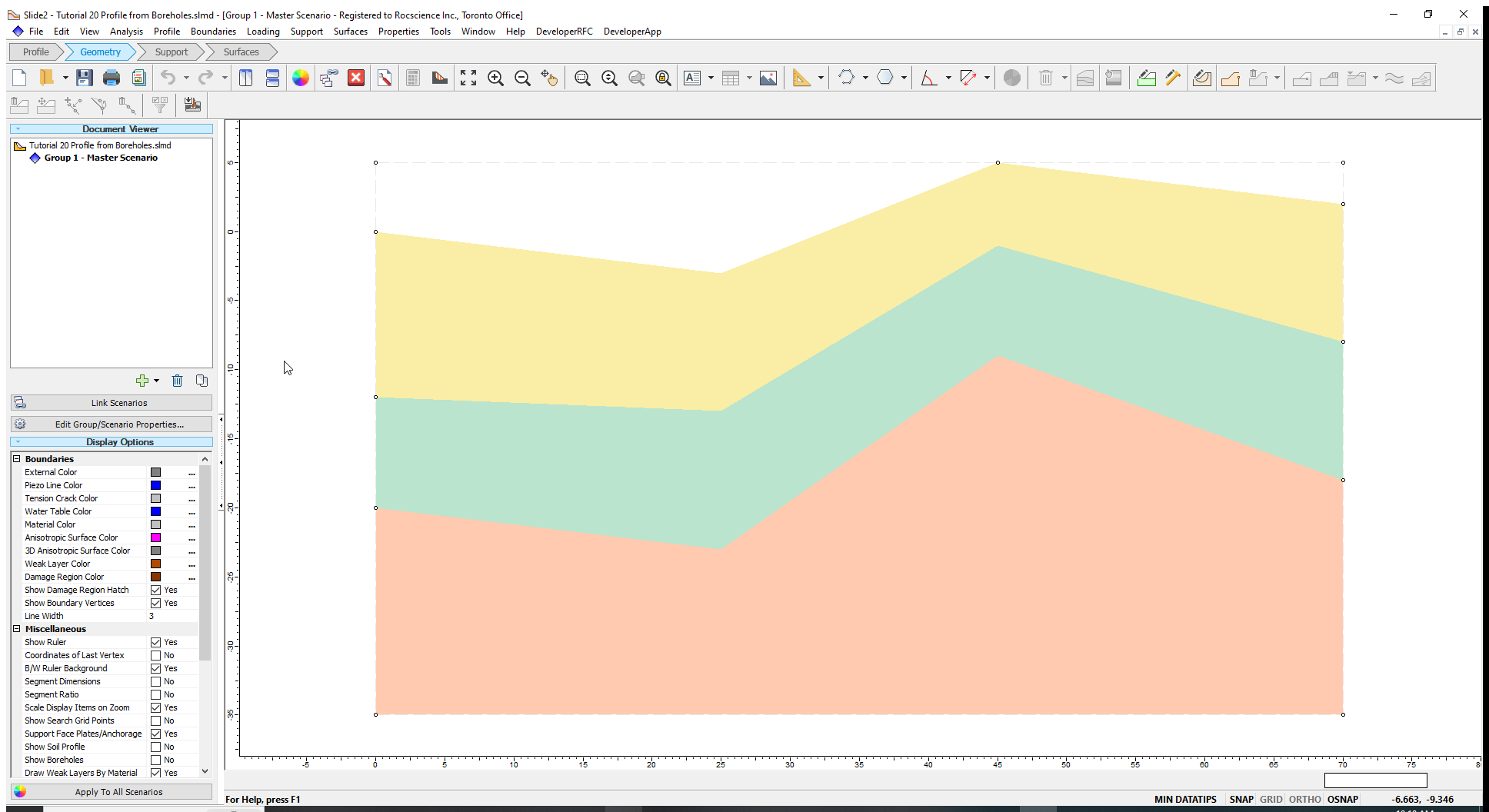
The profile boundaries and material assignments are displayed in a transparent shade in Geometry mode.
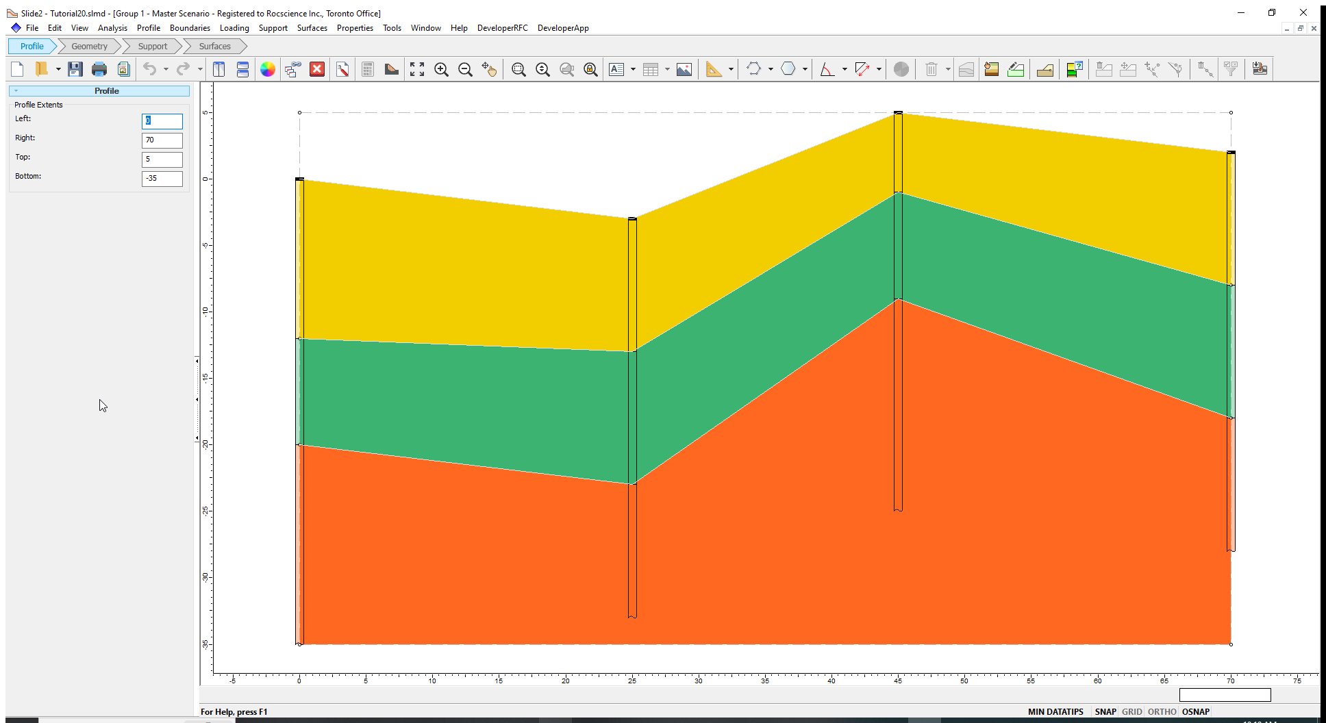
- To enable editing of the soil profile, select the Profile workflow tab. We can see the four boreholes on the profile.
- To see the soil profile from the boreholes, select Profile > Borehole Editor
 from the menu.
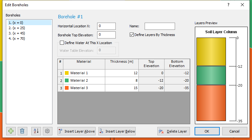
Click on the list on the left side of the Edit Boreholes dialog to see the input for each of the four boreholes.
To make the interpolated boundaries smooth:
- Click on Settings
 to open the Borehole Interpolation Settings dialog.
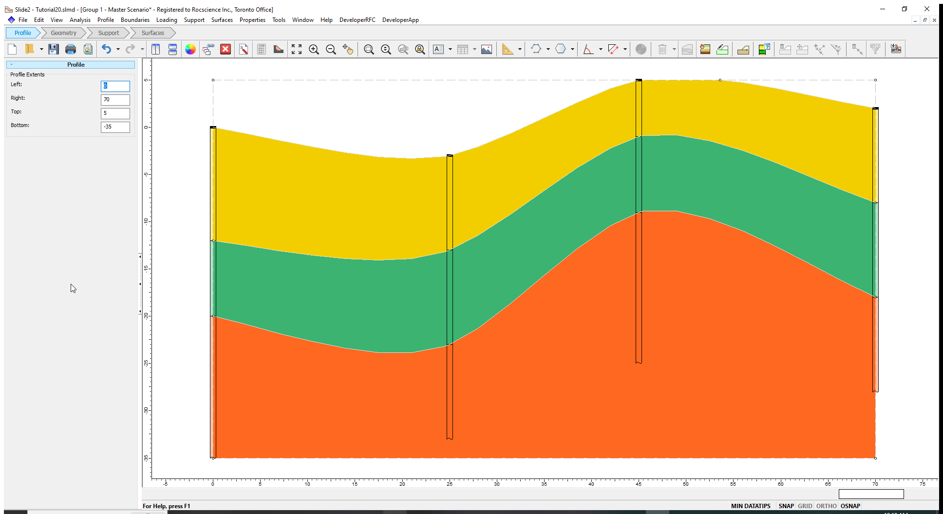
 - Change the Interpolation Method from Linear to Thin Plate-Spline as shown below. Do not change any other parameter.
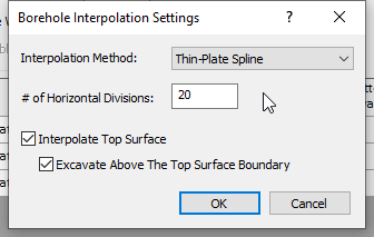
- Click OK on both dialogs to close them.
The interpolated boundaries are now smooth due to the spline curve fit of the borehole data.
You can also define a ground surface using the Add Soil Profile Boundary option, rather than having the ground surface automatically interpolated.
- Select Profile > Borehole Editor from the menu and click Settings
- Uncheck the box for Interpolate Top Surface.
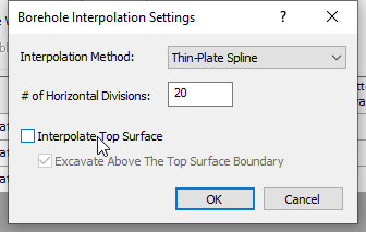
- Click OK on both dialogs to close and save the settings.
The model should look as below:
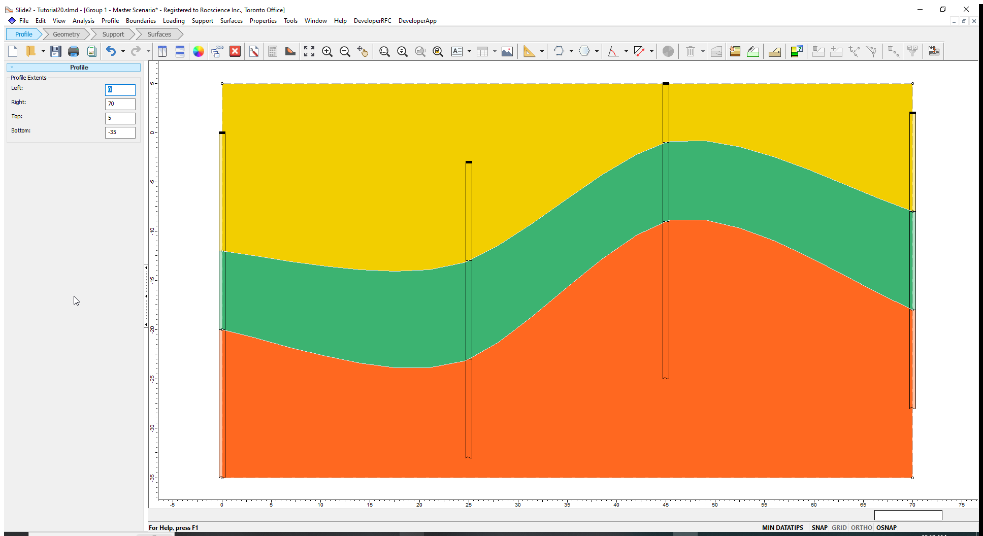
Notice that there is no longer a profile boundary through the top of each borehole, and the upper material assignment extends to the upper profile extent.
You cannot directly edit soil profile boundaries that have been interpolated from borehole data. You can only change the interpolation settings.
However, after defining the boreholes, you can add additional boundaries using the Add Soil Profile Boundary option if you need to modify or adjust the material regions.
Whether you define profile boundaries explicitly using the Add Soil Profile Boundary option, by interpolating borehole data, by importing a DXF, or some combination, the modelling procedure after defining the soil profile is the same in each case. You must define an external boundary in Geometry mode and proceed as usual to set up your analysis.