18 - Slope Angle Optimization
1.0 Introduction
In open pit designs, slopes are developed to be as steep as possible to minimize costs, while maintaining a suitable factor of safety.
In this tutorial, we will try to develop an optimal slope angle for an open pit excavated in weak rock. The specification of the mining company requires the factor of safety of the critical slip surface to be greater than 1.25.
In this tutorial, we will:
- Model different slope angles using the Slope Angle Wizard feature and
- Plot slope angle versus factor of safety to determine the optimum slope angle
The finished product of this tutorial can be found in Tutorial 18 Slope Angle Optimization.slmd data file. All tutorial files installed with Slide2 can be accessed by selecting File > Recent Folders > Tutorials Folder from the Slide2 main menu.
2.0 Model Geometry
- Select File > Recent Folders > Tutorials Folder in the Slide2 main menu.
- Open Tutorial 18 Slope Angle Optimization - starting file.slmd
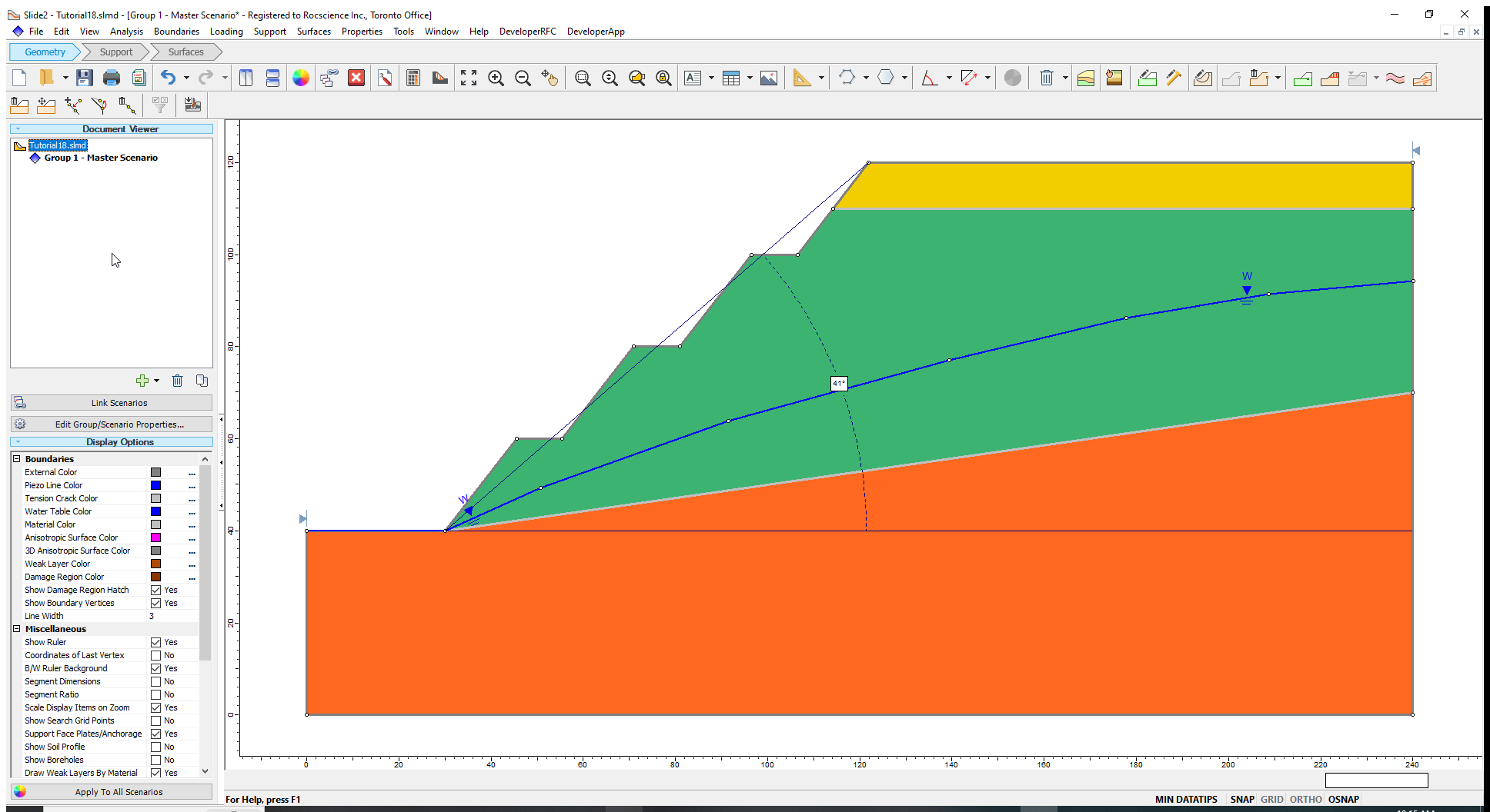
The initial model in the file is shown below.

- Select Properties > Define Materials
 to view the materials and their corresponding properties in the Define Material Properties dialog.
The slope materials consist of a layer of sediments and a weak weathered rock on top of bedrock.
Before we run a slope stability analysis to determine the safety factor for the Master Scenario, let us measure the overall slope angle.
- Select Tools > Dimension Angle
 to activate the angle measuring tool in Slide2.
 - Click on the crest of the slope and then on the toe of the slope to draw a line between these points.
- Drag the mouse to the right along the horizontal to draw the overall slope angle. The overall slope angle for the starting design is 41o. We will try to optimize this angle.
3.0 Computation and Interpretation
- Select Analysis > Compute
 to run the analysis.
 - Select Analysis > Interpret
 to view results when computations are done.
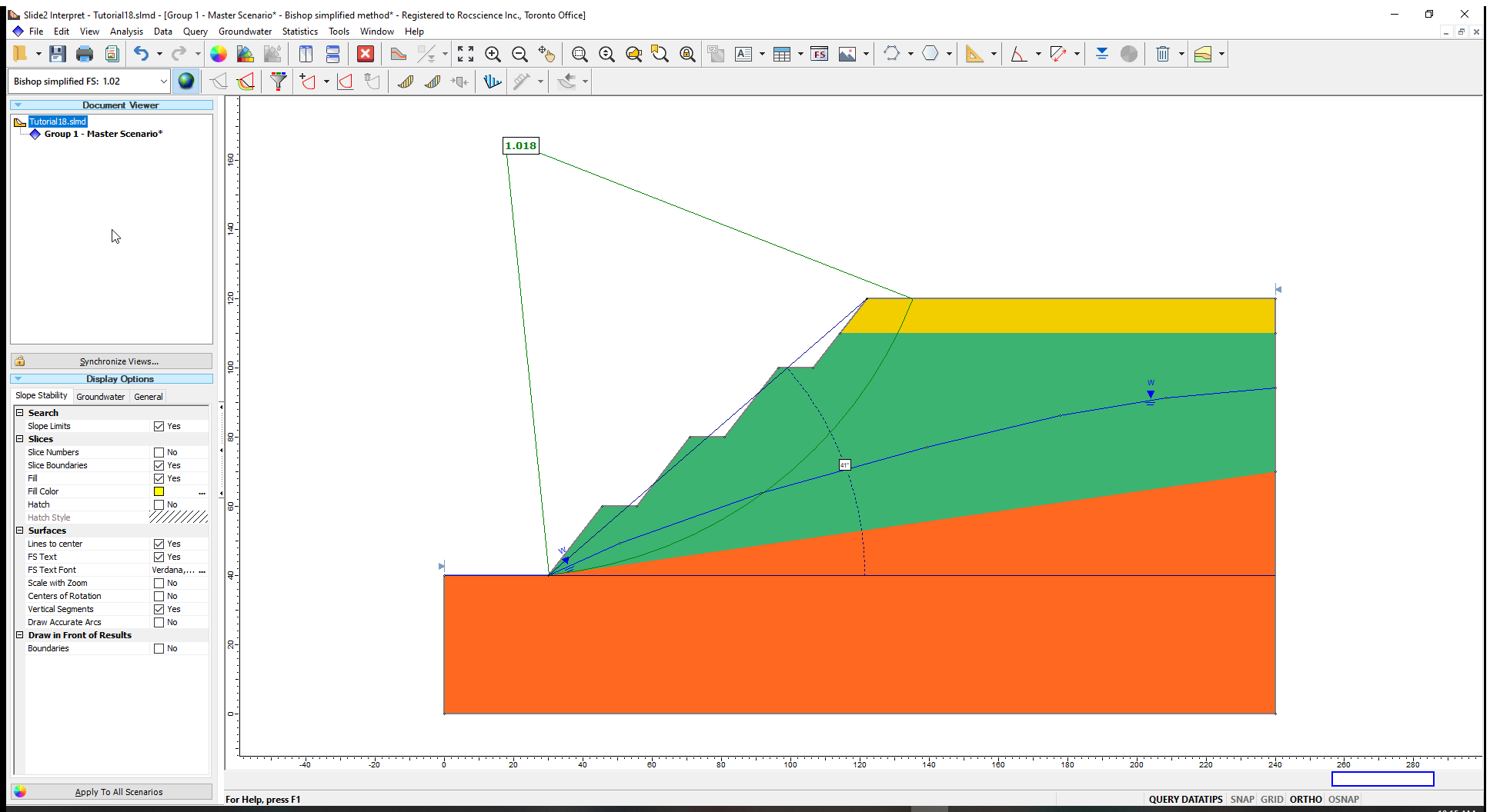
The factor of safety is about 1.0 which is less than the 1.25 safety factor required by the mine. The 1.0 value indicates a slope that is close to failure and is therefore inadequately designed. We will flatten the slope angle by various degrees and note the associated changes in the safety factor.
- Return to the Modeller.
4.0 Slope Angle Wizard
We will create four (4) different scenarios (groups) of the initial model, each with a different overall slope angle. We will decrease the slope angle by 4° in each subsequent scenario and run stability analysis on each of them.
- Select Boundaries > Slope Angle Wizard (Groups) to activate the Prompt line.
- Click on the starting vertex at the toe of the slope and then move the cursor along the slope face till it reaches the vertex at the crest of the slope. Click on the crest vertex to open the Slope Angle Wizard dialog. (Alternatively, you can enter the coordinates of the toe and crest – (30,40) and (122,120) – in the Prompt line.)
- Keep the default selection of Project Horizontally to adjust the slope in the horizontal direction.
- Select the Clockwise radio button. In our case, this option will generate flatter overall slope angles.
- Enter a value of 4 in the two fields for generating groups and specifying the increment angles as shown in the dialog below. (This means that we are generating four scenarios with overall slope angle decreased by 4° each time.)
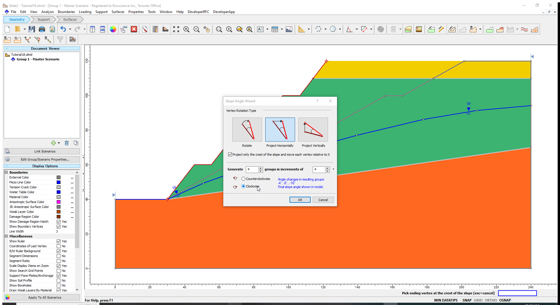
Please note that the checkbox labelled “Project only the crest of the slope and move each vertex relative to it” is ticked. This means the location of the toe will remain fixed and only the crest will move.
- Click OK to close the dialog.
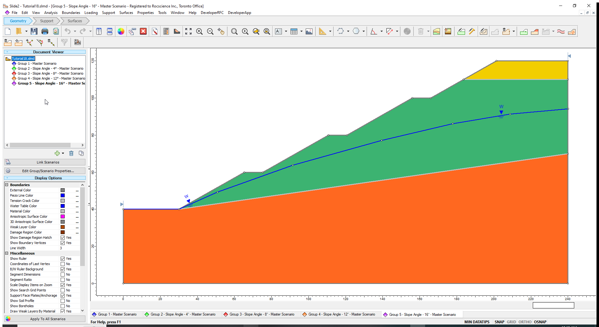
Four new groups are now created. Click on Group 2 – Slope Angle – 4 in the Document Viewer. The overall slope angle is equal to 37°, which results from subtracting 4 degrees from the initial value of 41°). As expected, the overall slope angle for Group 5 – Slope Angle – 16 is 25°.
Now, let us run the new models.
4.1 Computation and Interpretation
- Select Analysis > Compute and then click OK on the resulting dialog to run the analysis for the four new slope angle groups.
- Select
Analysis > Interpret and select the four groups to view results when the computations are done.
- Click on Tile Windows
 in the toolbar to see all the results simultaneously.
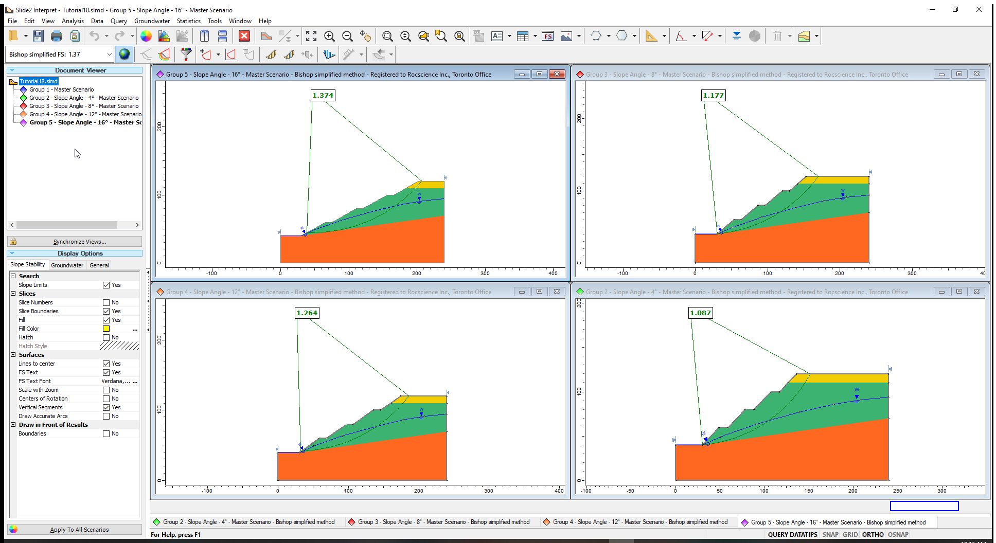
The critical slip surfaces and corresponding safety factors for the Bishop Simplified method are displayed for the groups as shown in the image above.
Let us see a plot of this data:
- Select Data > Graph Scenarios.
- Click Plot.
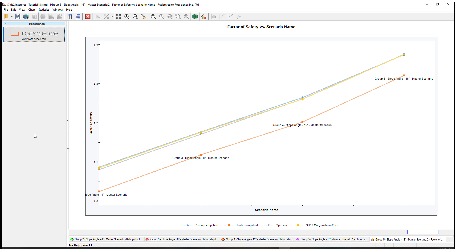
From the Bishop results, we can see that the optimum factor of safety of 1.25 can be obtained for an overall slope angle between ‘Slope Angle – 12°’ and ‘Slope Angle – 8°’ or, 33° and 29°.
5.0 Additional Exercise
Using interpolation, you can determine that the slope angle that gives a factor of safety of 1.25. Determine that angle, and then create a group with the final design.
- Return to Modeler, right-click on Group 1-Master Scenario and Duplicate the group. The new group is named Group 6-Master Scenario. Rename the group as ‘Final design’.
- Go to Boundaries > Change Slope Angle
- Select the toe of the slope and then the crest of the slope to open the Slope Angle Wizard dialog.
- Enter the rotation angle you determined and select the Clockwise rotation.
- Click OK to exit the dialog.
Compute the group and view the results to ensure you obtained the desired factor of safety of 1.25.
This concludes the tutorial on how to optimize a slope angle using the Slope Angle Wizard tool.