30 - Back Analysis
1.0 Introduction
This tutorial demonstrates the Back Analysis option in Slide2. The back analysis option allows you to determine the required force to achieve a desired factor of safety for a given slope. Before proceeding with the tutorial, it is helpful to complete Tutorial 07 – Support Tutorial to familiarize yourself with the Support feature used in this tutorial.
Topics Covered in this Tutorial:
- Support Back Analysis Feature
- Geosynthetic Supports
- Adding Support Patterns
- Slip Surface Boundaries
- Particle Swarm search (non-circular search)
Finished Product:
The finished product of this tutorial can be found in the Tutorial 30 Back Analysis.slmd data file. All tutorial files installed with Slide2 can be accessed by selecting File > Recent Folders > Tutorials Folder from the Slide2 main menu.
1.1 Overview
Back Analysis is a great tool for a preliminary design of a suitable system because:
- The required support force is calculated for a specified elevation for all analyzed surfaces.
- The critical surface requiring this force is displayed.
- It can be used with circular and non-circular surfaces.
Refer to the Back Analysis Overview page for more details.
2.0 Model (Default)
- Select File > Recent Folders > Tutorials Folders to open the Slide2 tutorials folder.
- Select Tutorial 30 Back Analysis – starting file.slmd and click Open.
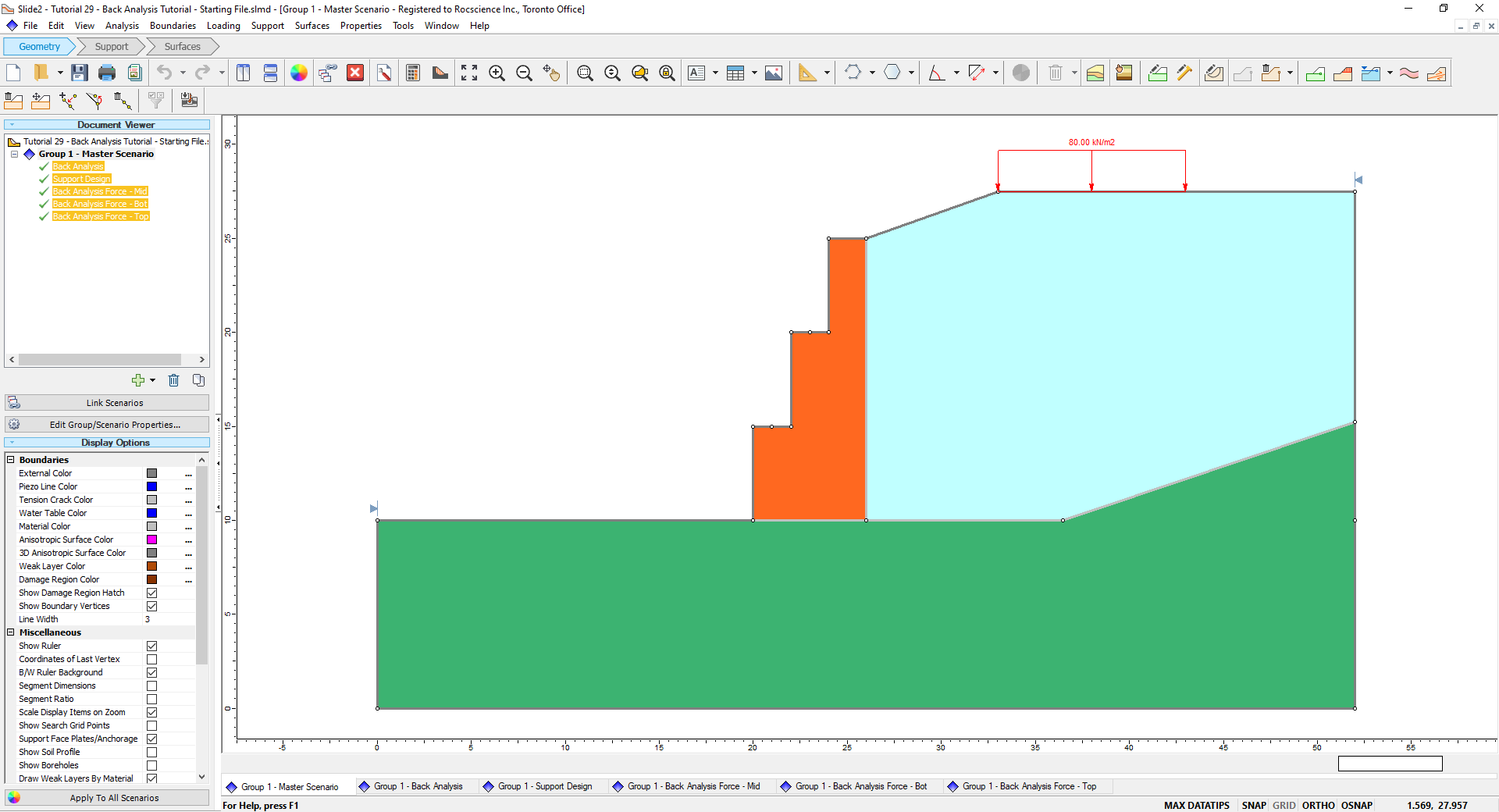
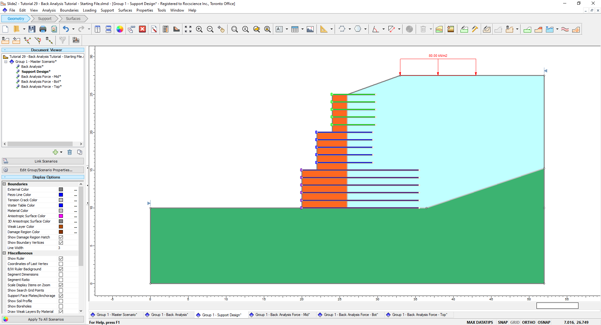
The starting file already defines geometry and material properties. The model is comprised of a retaining wall with 3 distinct levels. Notice 5 additional scenarios exist plus the master scenario. These will be used for the design process.
3.0 Compute and Interpret
We first want to verify the current slope is below our desired Factor of Safety (F.S.) and requires reinforcement. To ensure a safe design, we establish our desired F.S. as 1.5.
- Select Analysis > Compute
 and deselect all scenarios except ‘Group 1 – Master Scenario’ to only run that scenario.
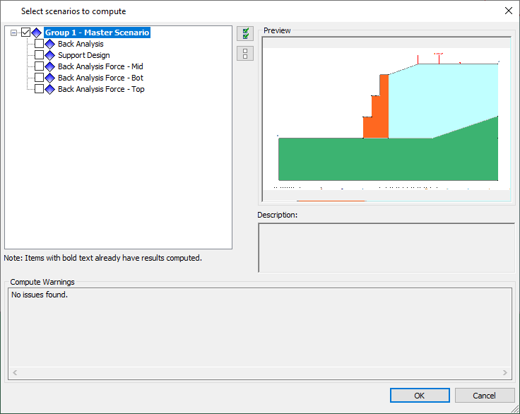
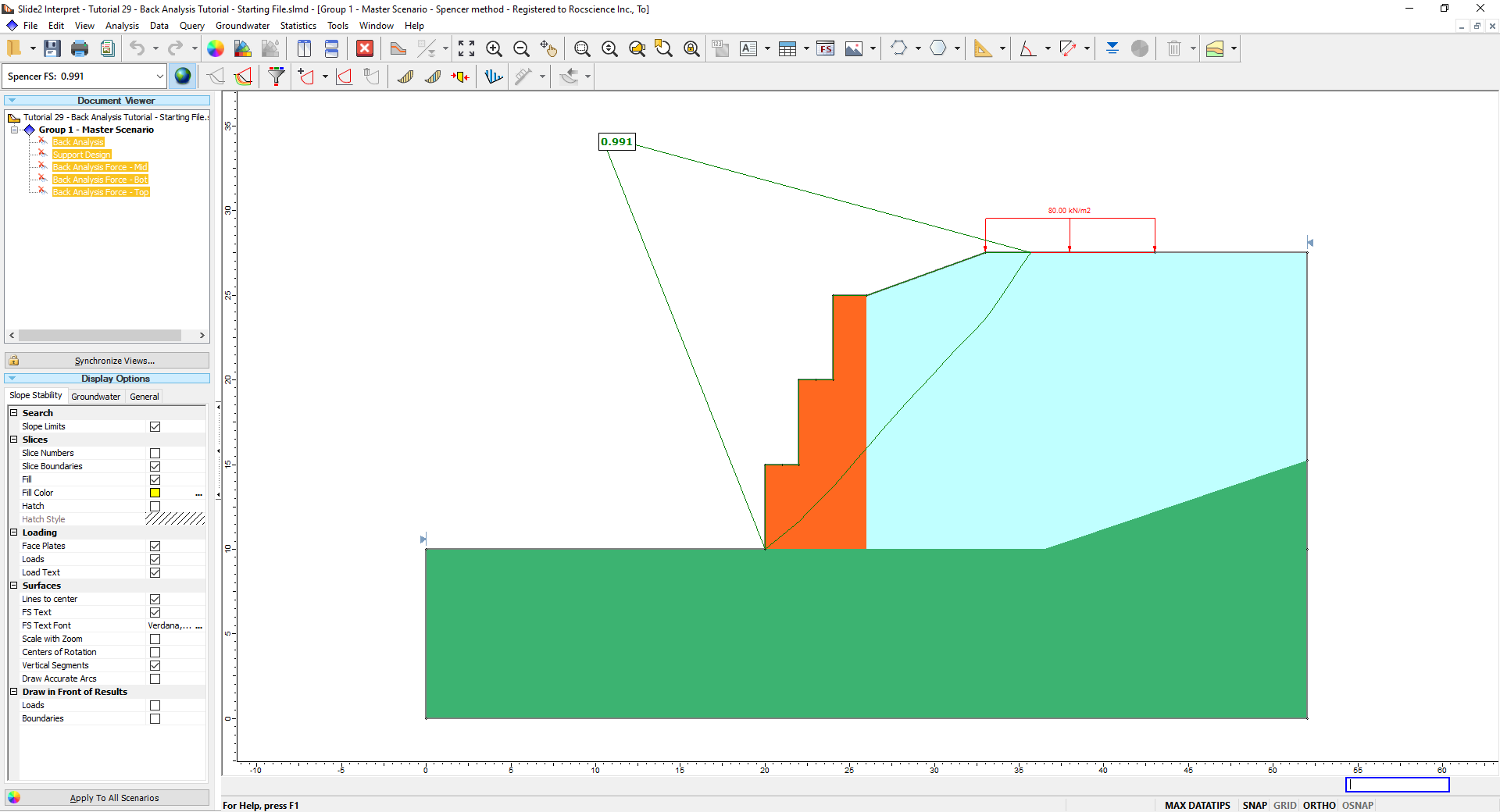
- When computations are done, select Analysis > Interpret
 to view the results. This will launch the Interpreter.
The F.S. is below 1.5. We need to add reinforcement to this retaining wall.
4.0 Back Analysis of Support Force
We’ll now perform a Back Analysis of Support Force on the wall to determine the required force for our support pattern to achieve a F.S. of 1.5.
- Close the Interpret
window to return to the Modeler
 and select the Back Analysis scenario in the Document Viewer.
 - Select Support > Back Analysis
 to open the Back Analysis of Support dialog.
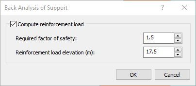
 - Tick the Compute reinforcement load option to activate the Back Analysis.
- Enter a Required factor of safety of 1.5.
- Because the critical surface is passing through the second wall, enter an elevation of 17.5 m as the Reinforcement load elevation, which is approximately the halfway point of the wall.
- Click OK.
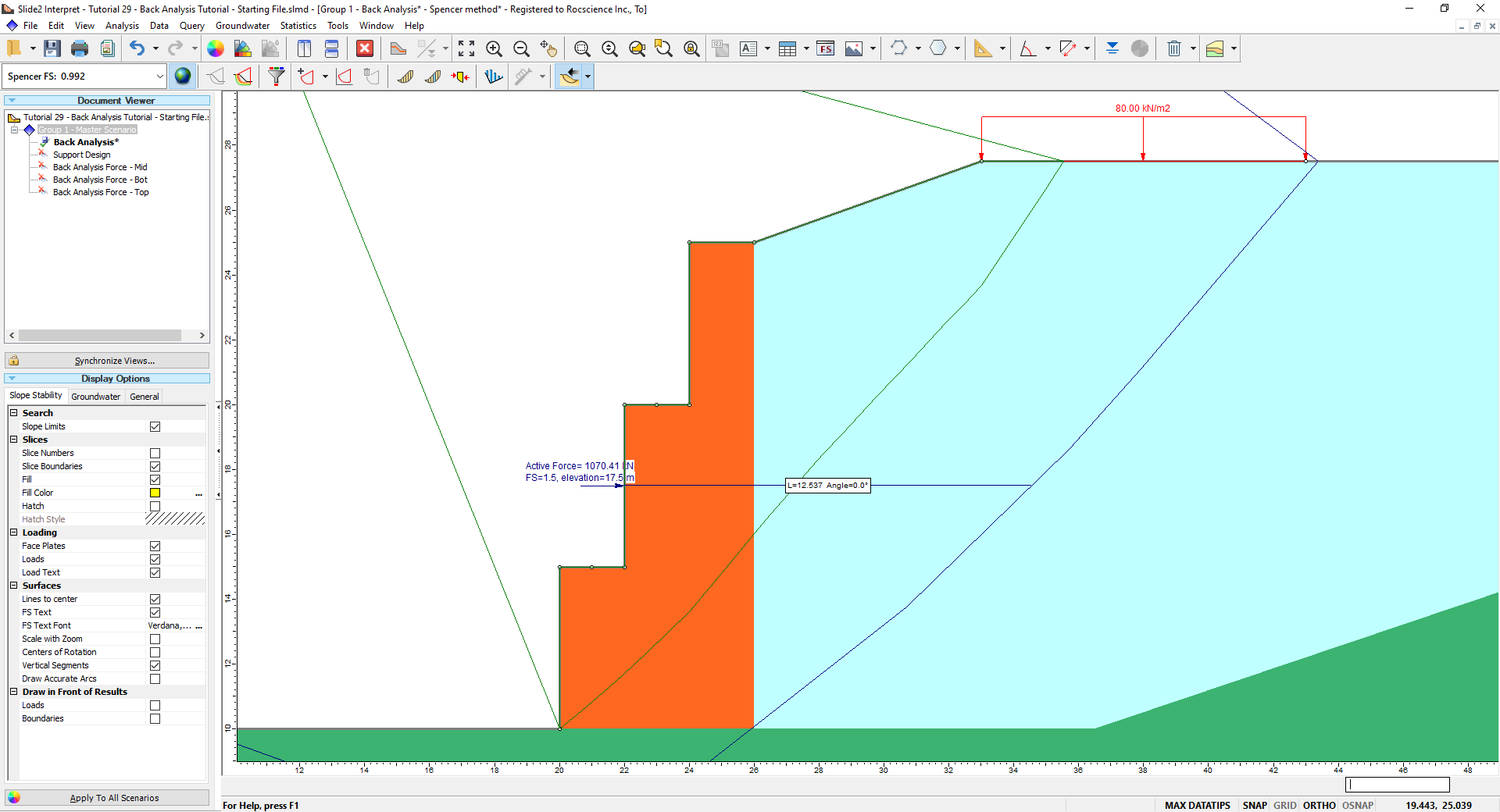
Notice a horizontal arrow now appears on the wall with the specified factor of safety of 1.5.
5.0 Design Using Back Analysis Results
Using the Back Analysis scenario results in the Interpreter, we can design the strength and length of each geosynthetic support in our pattern.
5.1 Compute and Interpret Results
- Like before, select Analysis > Compute. Select only the Back Analysis scenario and click OK to run that scenario. Select Analysis > Interpret to open the Interpreter like before.
- Ensure the force shown is active force by selecting Data > Back Analysis > Active Force in the menu, or selecting the Back Analysis
 drop down in the toolbar. Notice the force is now provided for the specific wall section (1077 kN) as well as the force type (active or passive). In addition, the critical surface requiring this force is also highlighted.
- We can distribute the force into 5 forces per support. This results in approximately 215 kN.
- Select Tools > Measure
 and select the location of the back analysis as the starting point. Alternatively, input (22, 17.5) into the Prompt line. Then, select the approximate horizontal distance at which the back analysis line intersects the highlighted critical surface. The distance should be approximately 13 m in this example.
Therefore, we can try an initial support design of 5 geosynthetic supports, each 13 m long with a strength of 215 kN/m each.
6.0 Initial Support Pattern Design
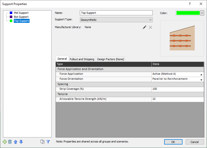
The geosynthetic supports used in this tutorial have already been defined. All that needs to be changed is the tensile strength.
- Close the Interpret
window to return to the Modeler and select the Support Design scenario.
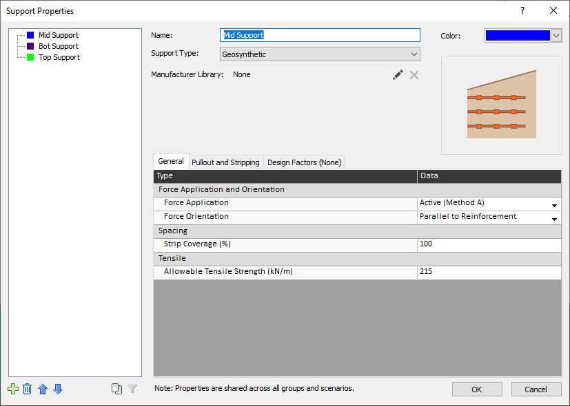
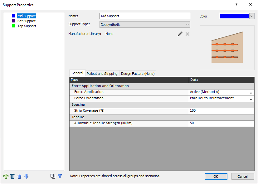
- Select Properties > Define Support
 . Select the Mid Support property type and enter an Allowable Tensile Strength of 215 kN/m. Click OK.
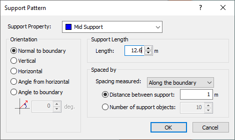
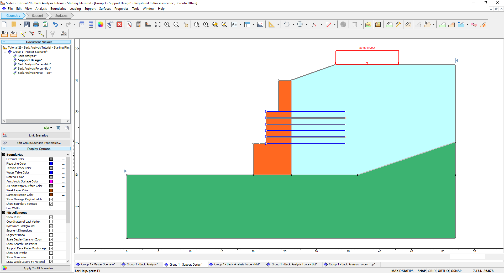
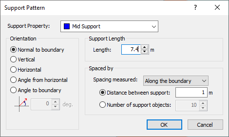
- Select Support > Add Support Pattern
 and ensure the Support property is the Mid Support property.
 - Input a Support Length of 13. Click OK.
- Select the top point of the middle wall (22, 20) as the first point and select the bottom of the wall (22, 15) as the second point. There shoud be a total of 6 supports on the wall.
- Select Analysis > Compute . Choose only the ‘Support Design’ scenario to run. Open the Interpreter
like before.
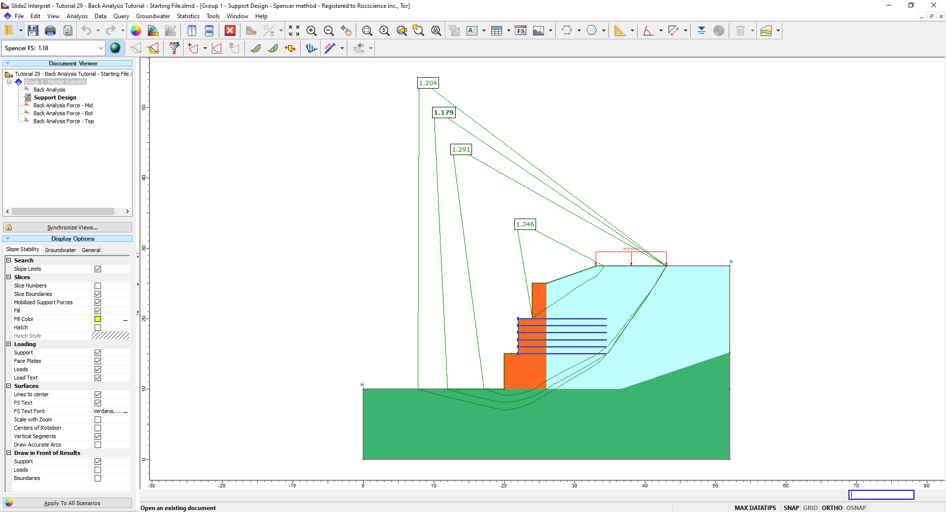
The critical surfaces were determined using Particle Swarm search with Multiple Mins for Spencer’s method. What we see is not only are all surfaces below our desired factor of safety of 1.5, but there now appears to be a more localized failure on the top level. We need to add to our support design.
7.0 Design Using Multiple Back Analysis Results
To complete our design, we need to account for each section of the wall using a combination of Back Analysis results and slope limits to target localized slip surfaces.
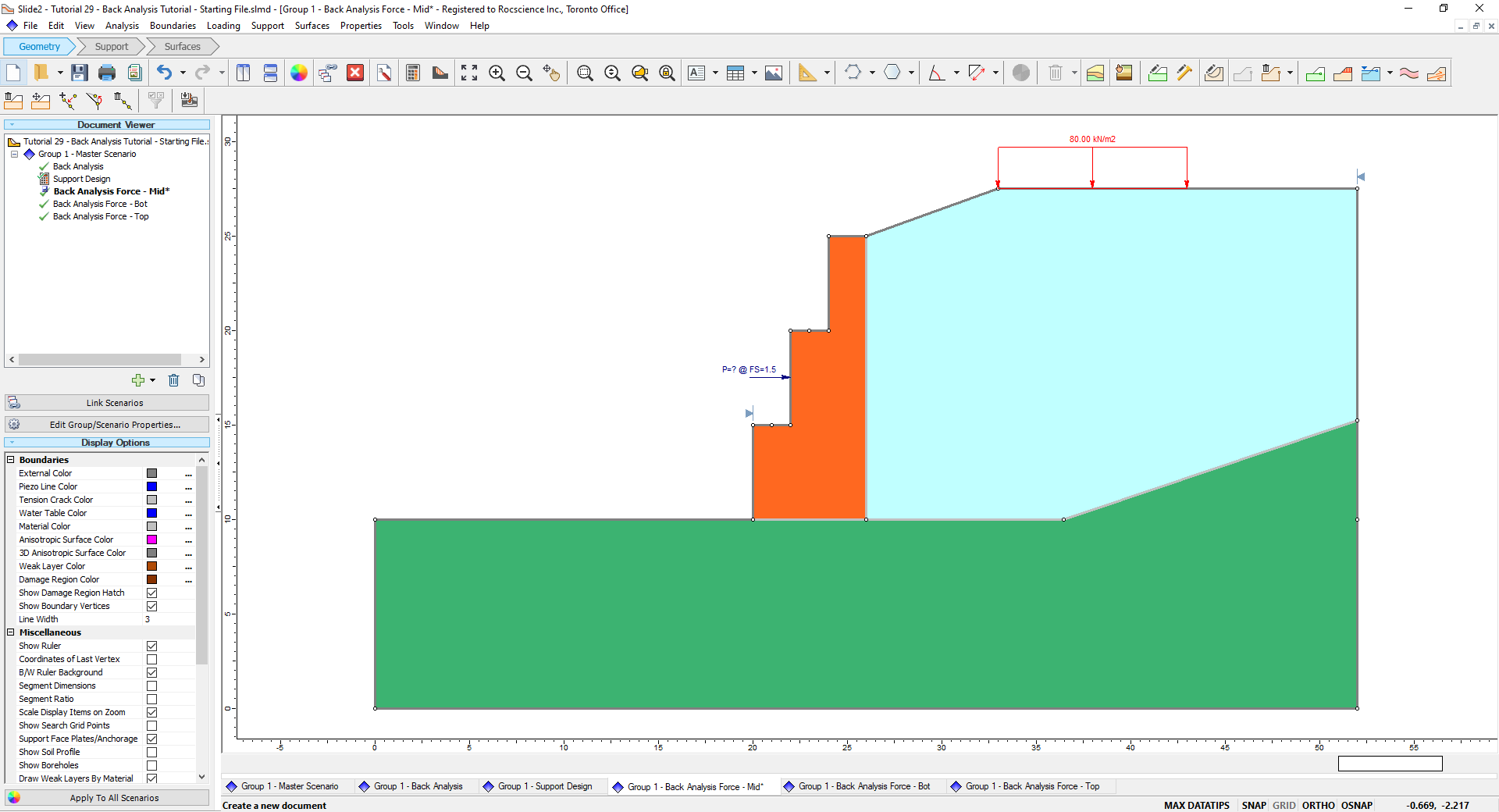
- Close the Interpreter, return to the Modeler and select the Back Analysis Force – Mid scenario.
- Select Support > Back Analysis and tick Compute reinforcement load as before. Ensure the required factor of safety and elevation are still 1.5 and 17.5 m respectively. Click OK.
- Right-click the left slope limit and select Move Limits (or select Surfaces > Slope Limits > Move Limits in the menu). Use your mouse to drag the left slope limit to the edge of the second wall (20, 15).
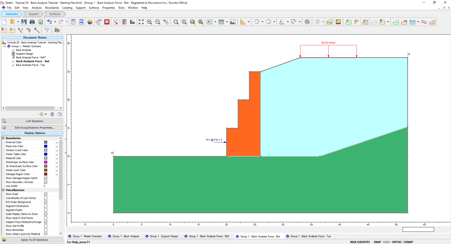
- Normally, we would now repeat this process for the other 2 scenarios. To save time, the other 2 scenarios have already been set and you should see each Back Analysis of Support Force at a different elevation and altered slope limits.

7.1 Compute and Interpret Results
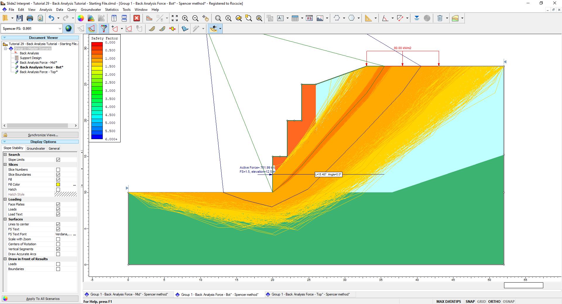
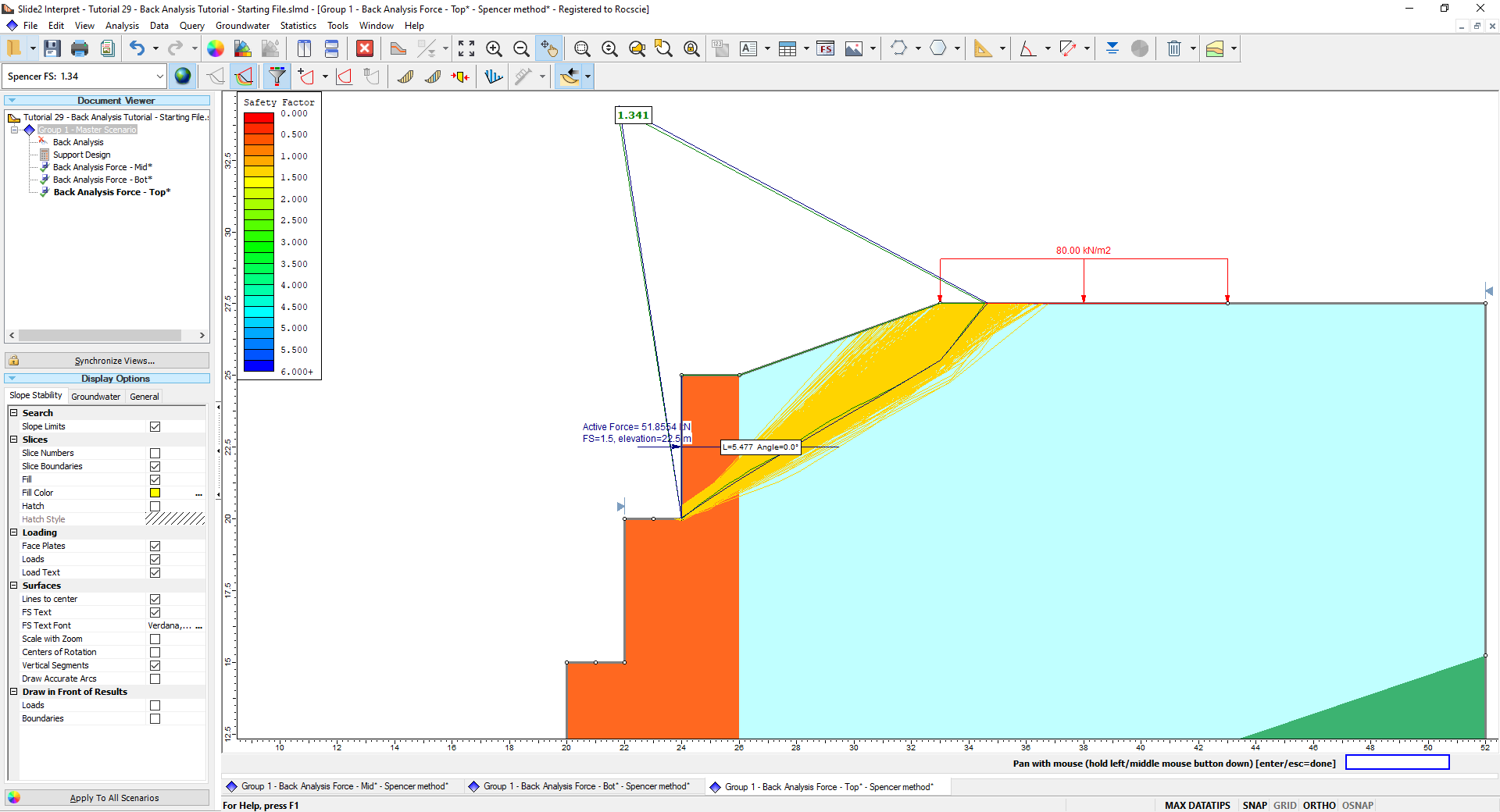
- Select Analysis > Compute to compute all three Back Analysis Force (mid, bot, top) scenarios. Open the Interpreter . When viewing all three scenarios, we see three distinct forces for each Back Analysis at their respective elevations.
- For the Mid level scenario, click the Back Analysis dropdown arrow in the toolbar (or Data > Back Analysis in the menu) and select Show all surfaces with FS less than 1.5. This will display surfaces like the Filter Surfaces option.
- Select Tools > Measure and select the location of the Back Analysis of Support Force as the first point and the horizontal intersect of the horizontally DEEPEST surface shown on the band, NOT the critical Back Analysis surface.
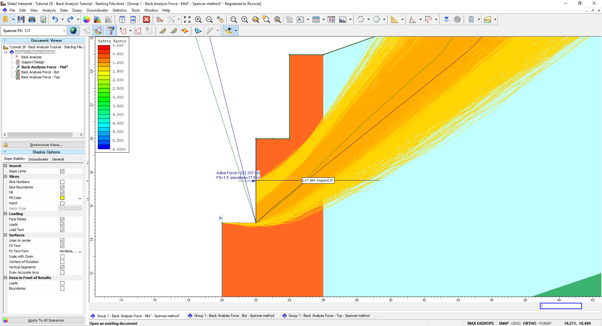
- Repeat the steps for the other two scenarios. Results are summarized in the table below.
| Wall Level | Back Analysis Force (kN) | Distance to Deepest Surface (m) | Design Strength per Support (kN) |
| Middle | 223 | 7.0 | 50 kN |
| Bottom | 716 | 15.1 | 150 kN |
| Top | 46 | 5.0 | 10 kN |
- We determine the approximate design strength by dividing the force by 5 for each support.
7.2 Utilizing Slope Limits and Failure Band for Design
The strength of the Back Analysis tool lies in its ability to find the maximum force for ANY valid surface it contacts. In most scenarios, it is unlikely a singular force is supporting an entire slope, especially in this example with multiple vertical faces. However, the Back Analysis of Support Force will still identify a significantly large and deep soil mass. This can lead to overconservative forces, as shown with our initial Back Analysis of Support Force we first found at the middle level.
As an example, consider if only one back analysis of support force is calculated at the top wall of this slope with unaltered slope limits. This will catch any surface it touches, including significantly deep slopes reaching near the bottom of the slope. However, since the moment arm of a support at the top level is significantly less than a support at the bottom level, the restoring force required to achieve the specified factor of safety is significantly higher at the top level.
Altering the slope limits allows the back analysis of support force to identify the critical slip surface LOCAL to the vertical face. Then, using the deepest surface in the now localized band allows us to consider the maximum force and length simultaneously to design a suitable support. Deeper slopes can be adequately accounted for by the bottom supports which have a much greater moment arm to provide a restoring support force. Repeating this for the other vertical faces allows us to design a support appropriate for each wall level, mitigating suboptimal designs.
8.0 Improved Support Pattern Design
Using the Back Analysis results, we can apply the new support patterns to each section of the wall.
- Click Save
 and then close the Interpreter. In the Modeler, select the Support Design scenario once again.
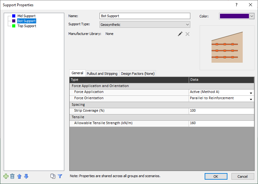
 - Select Properties > Define Support and change the Allowable Tensile Strength of each support based on the respective required strength in the previous step (see section 7.1). Click OK.
- Delete the existing support in the middle wall by right-clicking the support pattern and selecting Delete Pattern. Select Support > Add Support Pattern to add the new support pattern.
- For the Mid Support property, set the Length to 7.0 m. Click OK.
- Select the top of the middle wall as before and add 5 supports along the wall.
- Repeat for the other two scenarios. For the bottom wall, input a length of 15.1 m and add one additional support (total of 6). For the top wall, input a length of 5 m for the length and add 5 supports.
8.1 Compute and Interpret Results
- Compute (select Analysis > Compute ) and choose only the ‘Support Design’ scenario to be computed.
- Open Interpreter to view the results.
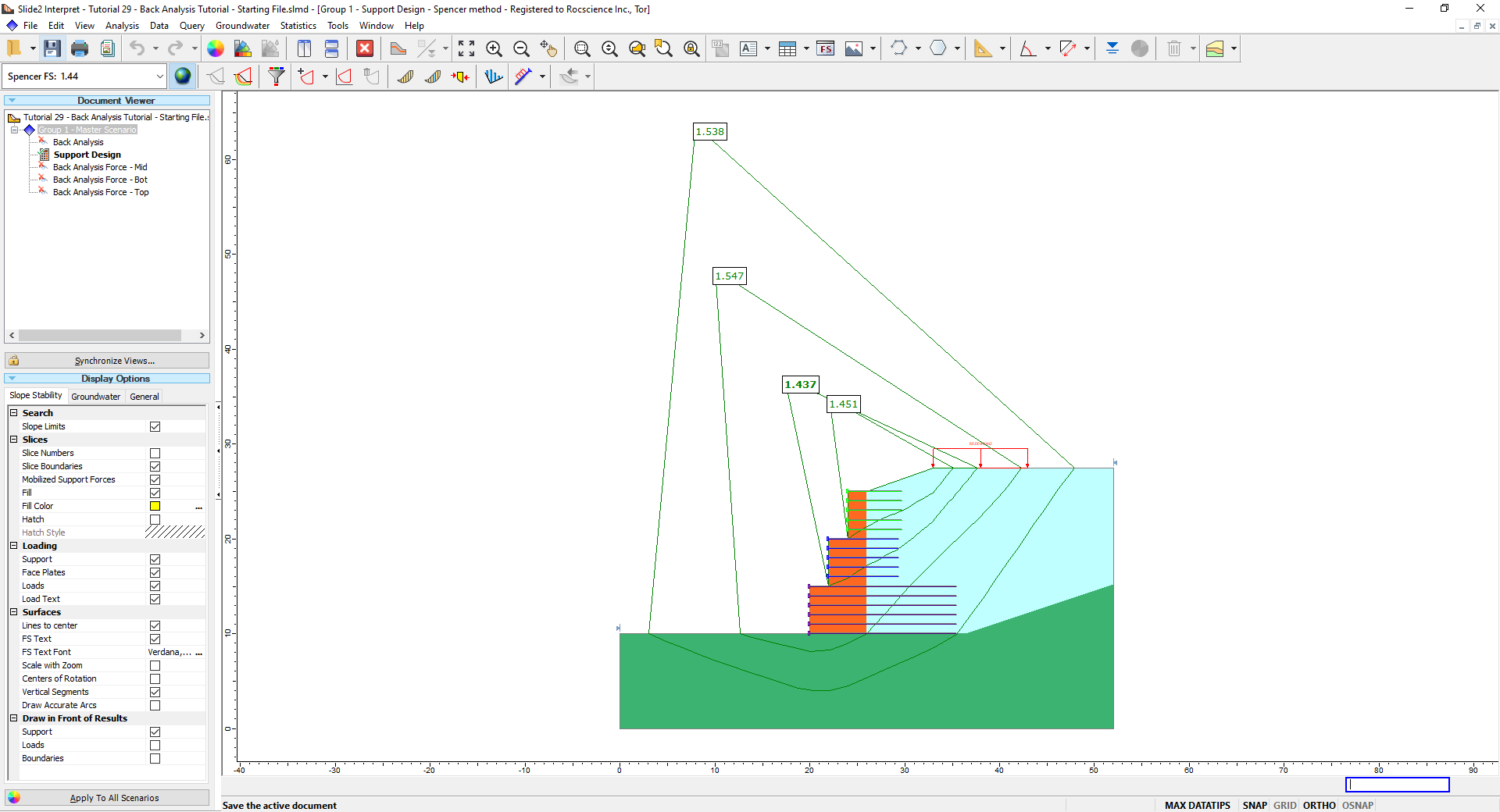
The results are much better compared to our initial design. As for the more localized failures in the upper two walls, the factors of safety are very close to 1.5. These upper supports can now be adjusted by extending the supports, increasing their strength, or any combination of both. For example, you can increase the length of the top and middle supports to 8 m and 10 m respectively to achieve factors of safety greater than 1.5. Alternatively, you can increase the top and middle support strengths to 20 kN and 75 kN respectively.
9.0 Additional Exercise
The top and bottom wall Back Analysis model presets were determined using the same process covered for the middle wall. As an additional exercise, consider creating the scenarios with the appropriate Back Analysis elevation and slope limits as well as determining the required force and length as provided in the tutorial.
In addition, consider altering the length and/or strength of the final supports such that a factor of safety of 1.5 is achieved.
10.0 Summary
This tutorial demonstrated the capability of the Support Back Analysis feature to design initial support patterns for slope stability. Using the process shown here, you can now quickly design multiple support types even for more complex scenarios such as the retaining wall covered in this tutorial.
Ultimately, iteration is necessary to achieve an efficient design and other models may not immediately provide desired results. However, using the Back Analysis feature significantly expedites this process and is a reliable starting point in designing support patterns.