Reinforced Slope
1.0 Introduction
This tutorial will demonstrate how support such as soil nails, tiebacks or piles can be added to a slope model. Results will be compared before and after adding support.
The model is a simple homogenous extruded slope. All properties and settings have already been defined, but the support has not yet been added.
To begin:
- Select File > Recent > Tutorials and open the file Reinforced Slope – starting file from the installation folder.
2.0 Compute and Results
- Select Analysis > Compute
 to run the analysis
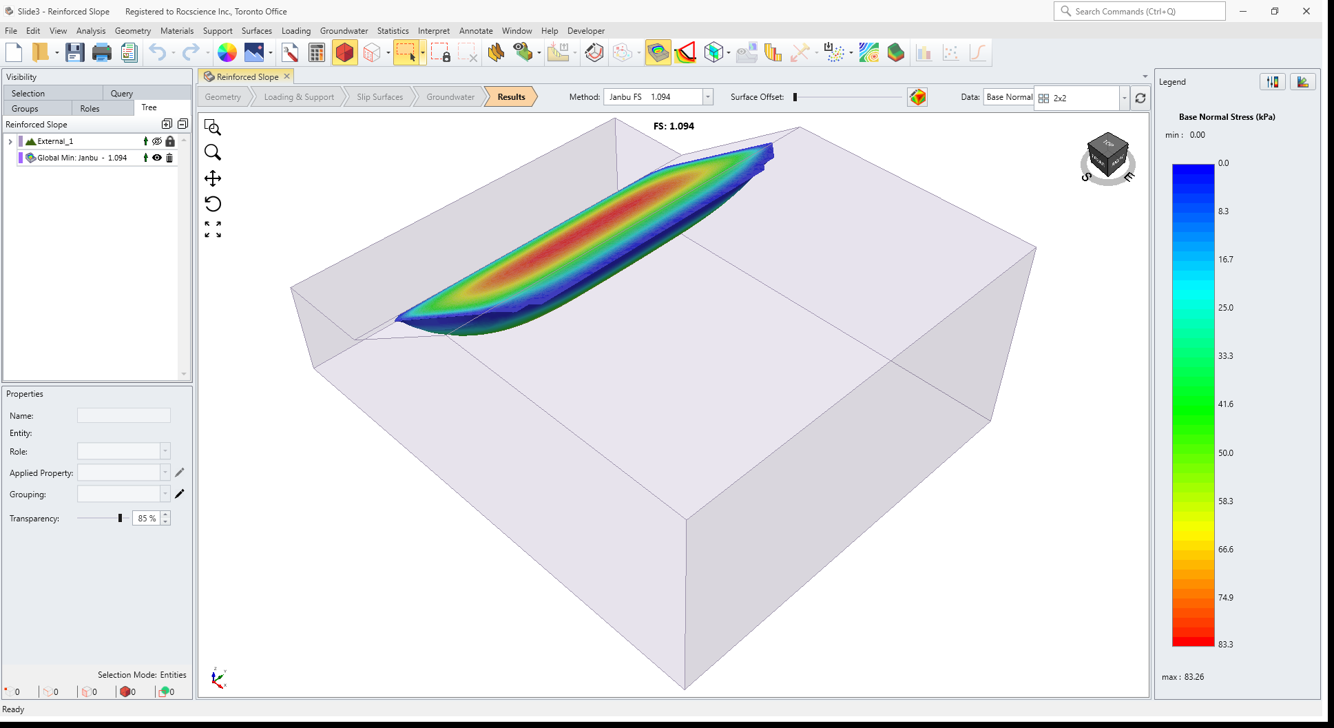
 - Select the Results workflow tab
 to view the results.
 - Then, click the Show Contours
 option in the toolbar.
The factor of safety using the Janbu method is about 1.1 for the unsupported slope.
3.0 Export Surface Results
For comparison with the model after we add support, let’s export the critical slip surface for the unsupported slope.
- Select Interpret > Export Surfaces > Export Slip Surface and save the file as a “Slide3 Result Object” file (with a *.slide3dresobj file extension).
This file can later be imported for comparison with the supported results.
4.0 Define Support
- Select the Loading & Support workflow tab.
- Select Support > Define Support

- For the first support type, enter:
- Name = Soil Nail,
- Tensile Capacity = 150
- Plate Capacity = 150 and
- Bond Strength = 85.
5.0 Add Support
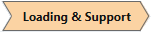
Now we will add a pattern of soil nails to the slope face.
- Select Face
 selection mode and click on the slope face of the model.
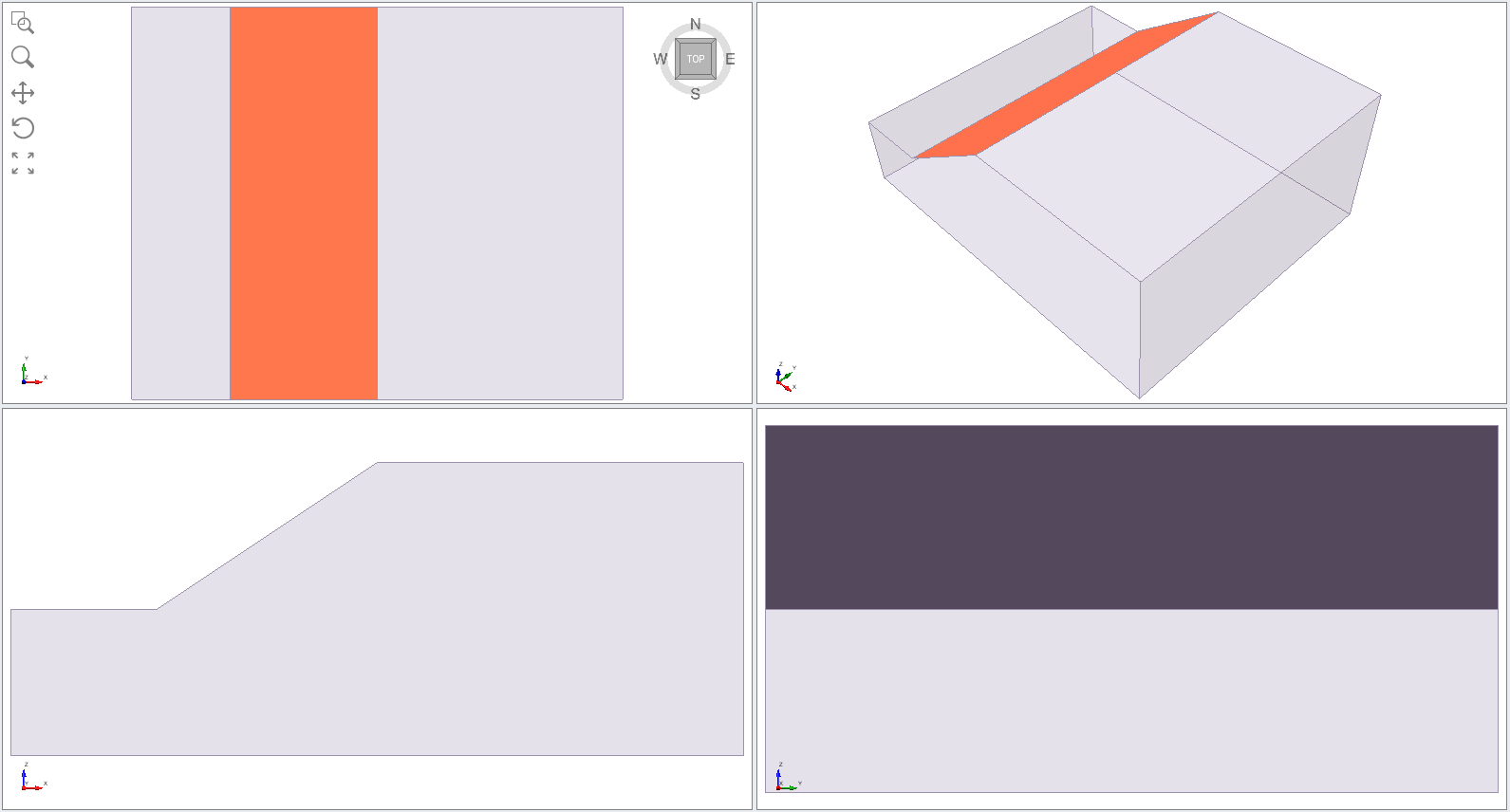
- Select Support > Add Support to Surface

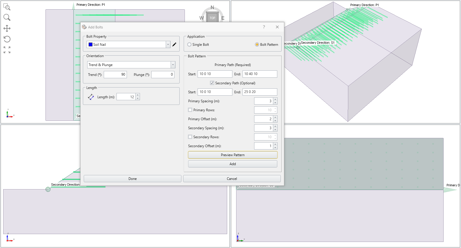
- You will see the Add Bolts dialog. In this dialog:
- Select Orientation = Trend & Plunge
- Enter Trend = 90, Plunge = 0
- Enter Length = 12
- Select Application = Bolt Pattern
- Primary Path (Required)
- Start = 10 0 10
- End = 10 40 10
- Secondary Path (Optional) = YES
- Start = 10 0 10
- End = 25 0 20
- Primary Spacing (m) = 3
- Primary Offset (m) = 2
- Secondary Spacing (m) = 3
- Secondary Offset (m) = 1
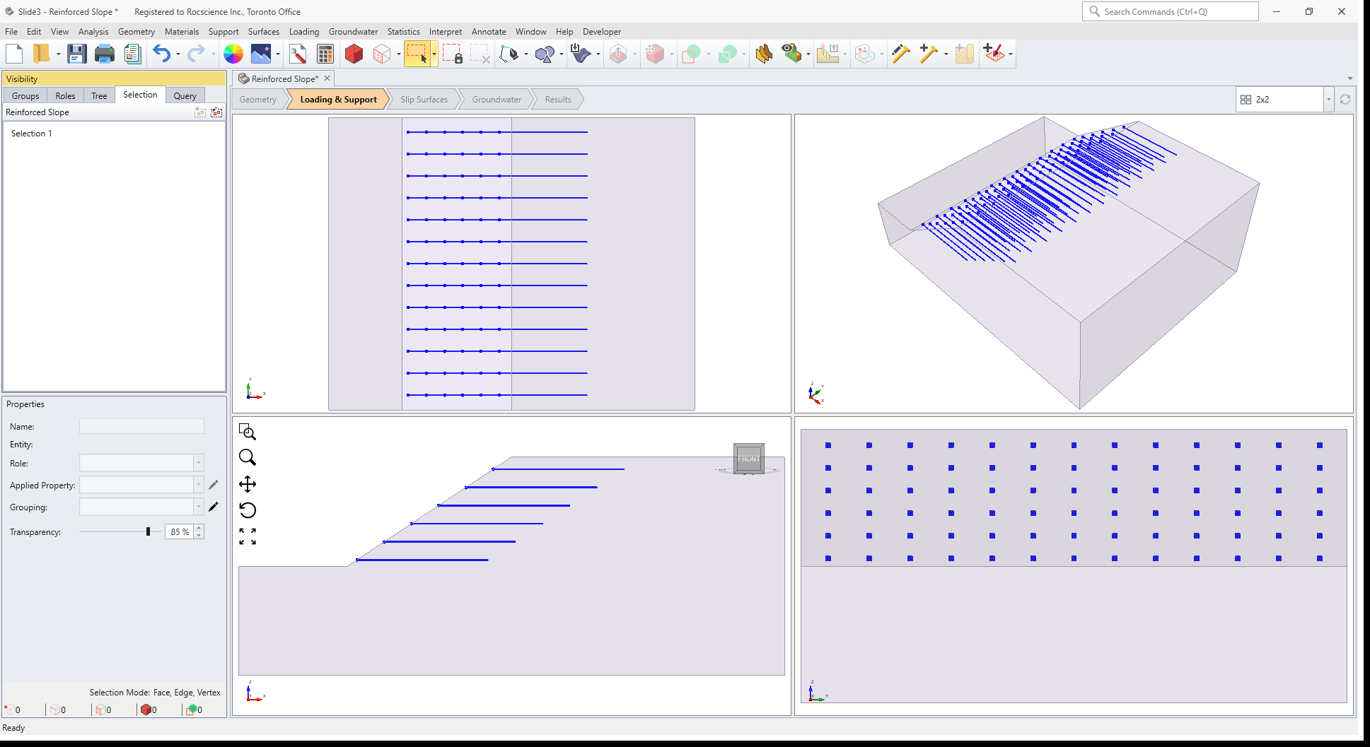
6.0 Results
- Save the file and Compute
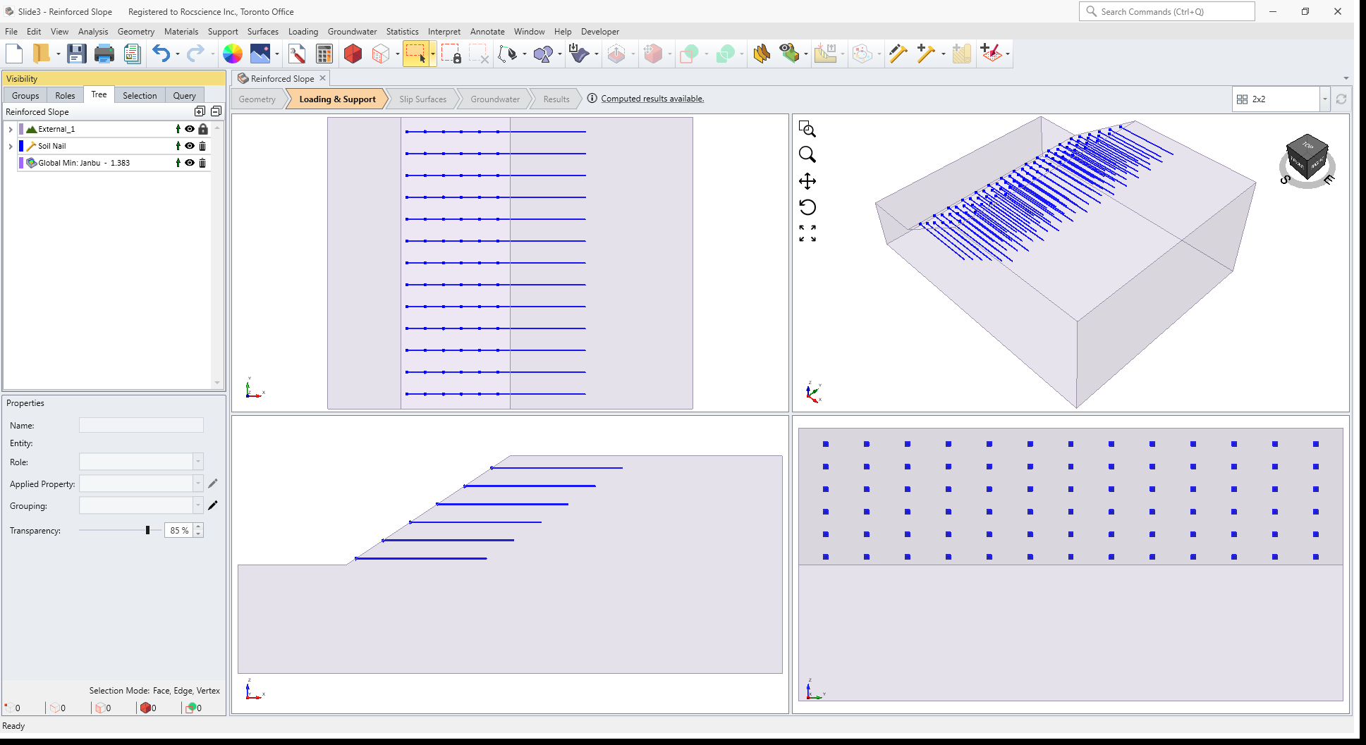
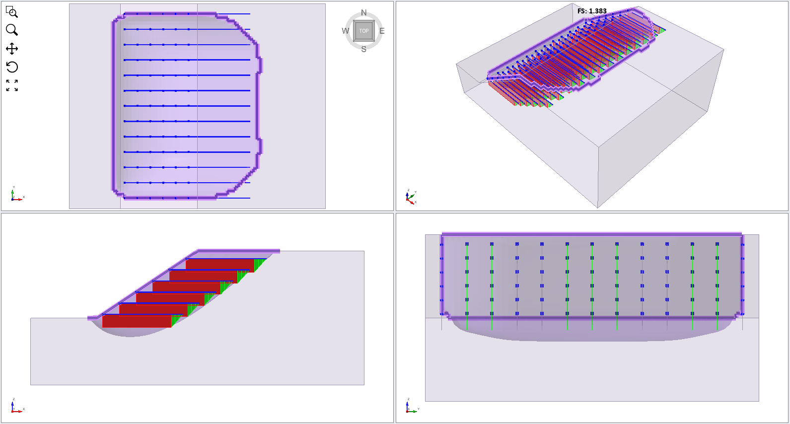
- Select the Results workflow tab to view the results. Select the Show Contours option in the toolbar.
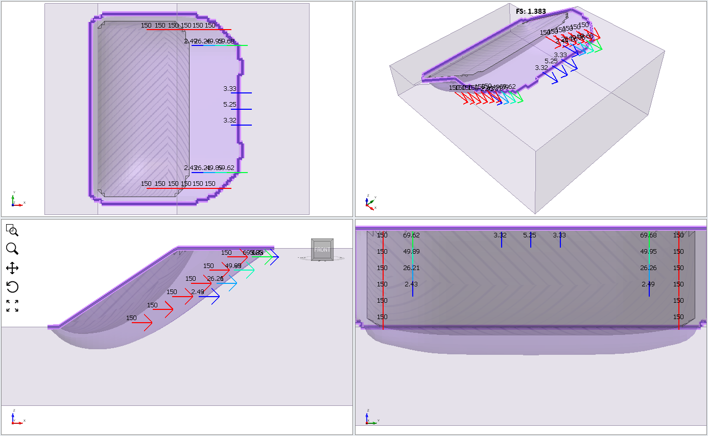
The factor of safety for the Janbu method is about 1.3 (compared to 1.1 for the unsupported slope).
Reinforced Slope: Results View Tab - with Support - Turn off the Show Contours option.
Bolt Result Display Options
We will now demonstrate display options for bolt results.
- Turn off the contour option by re-selecting Show Contour option.
This is important because these are the bolts which stabilize the slip surface. Bolts which do NOT intersect a slip surface have no effect on the safety factor of that slip surface.
Bolts which intersect slip surface - Select Interpret > Show Bolt Force Diagram.
The bolt force diagram is derived from the bolt support properties and represents the maximum support force which can be applied to a slip surface intersecting a bolt along its length. The colour of the diagram represents the potential failure mode (e.g. tensile, pullout or stripping). See Slide3 help for more information on bolt force diagrams.
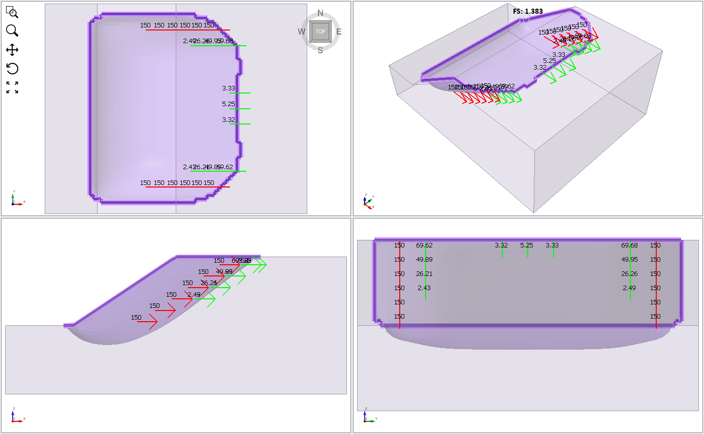
Bolt force diagrams displayed on bolts The Show Bolt Column Forces option will display the actual support force applied to the slip surface by each bolt used in the analysis.
- Select Interpret > Show Bolt Column Forces.
The Show Intersecting Bolts  option will display only the bolts which intersect the slip surface.
 The Show Bolt Force Diagrams option will display the bolt force diagram for each bolt directly on the bolt.
The colour indicates the failure mode, in this case, green = pullout. Notice that the Legend at the right of the screen indicates the bolt failure modes and force magnitudes.
Display Options
- Select Display Options
 from the toolbar menu
 - Select the Bolt Forces tab. You will see additional options for customizing the display of bolt results.
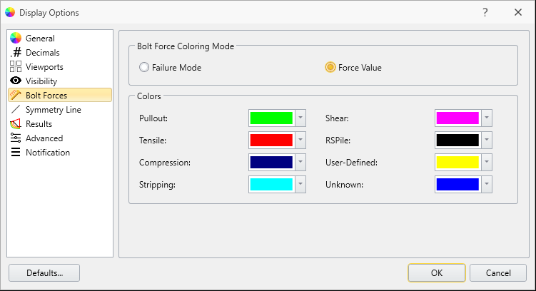
Display Options dialog If you select Bolt Force Coloring Mode = Force Value, the magnitude of the bolt forces will be indicated by the displayed colour as shown in the Legend.
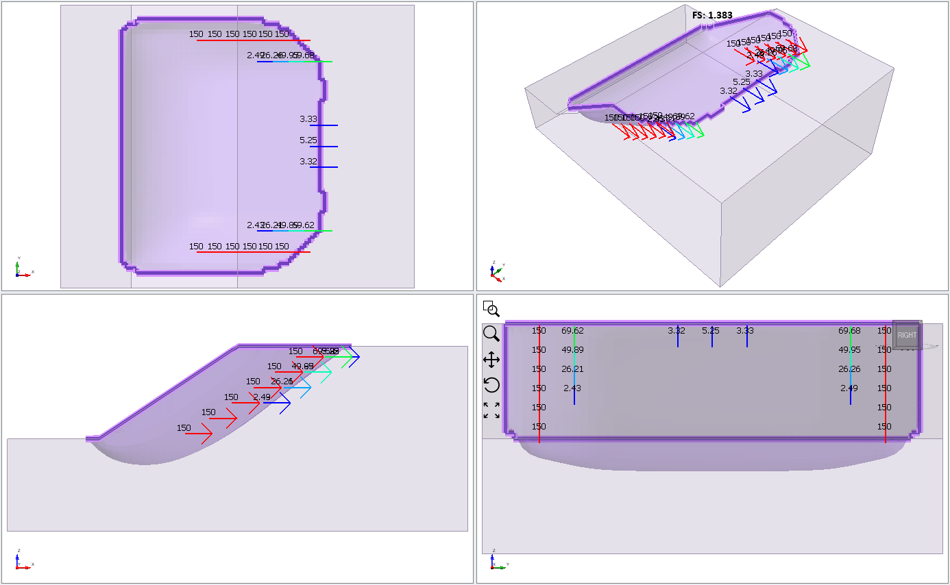
Bolt Forces Magnitude Displayed - Turn off all of the bolt display options except for the Show Intersecting Bolts option (leave this on).
7.0 Import Surface Results
Now we will import the critical slip surface obtained from the analysis of the un-supported slope, and compare with the supported results.
- Select Interpret > Import Surfaces > Import Slip Surface and import the Slide3 Result Object.slide3dresobj file you saved at the beginning of this tutorial.
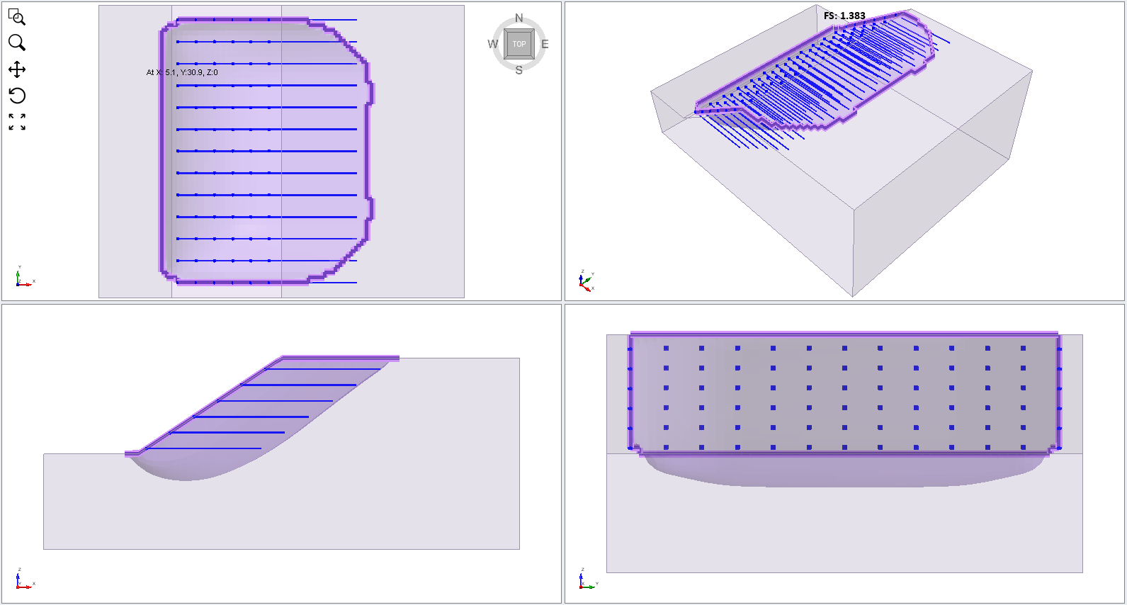
The geometry of the slip surface should be imported, and you should see the following:
This clearly shows the effect of the bolt support. The unsupported slip surface is shallower and has a safety factor = 1.1. In comparison, the bolt support has forced the critical slip surface deeper into the slope and increased the safety factor to 1.41.
This concludes the Reinforced Slope tutorial.