Creating Geometry with Slope Wizard
1.0 Introduction
In this tutorial we will be creating a 3D slope profile using Slide3's Slope Wizard tool. The Slope Wizard is very useful for quickly creating 2D extruded models for demonstration or teaching purposes. The following includes some of the features:
- Creates an extruded 2D slope geometry based on user-defined slope dimensions and angles,
- Allows the user to define multiple soil regions (e.g. weak layers) and assign material properties to each of these regions,
- The External volume is automatically defined.
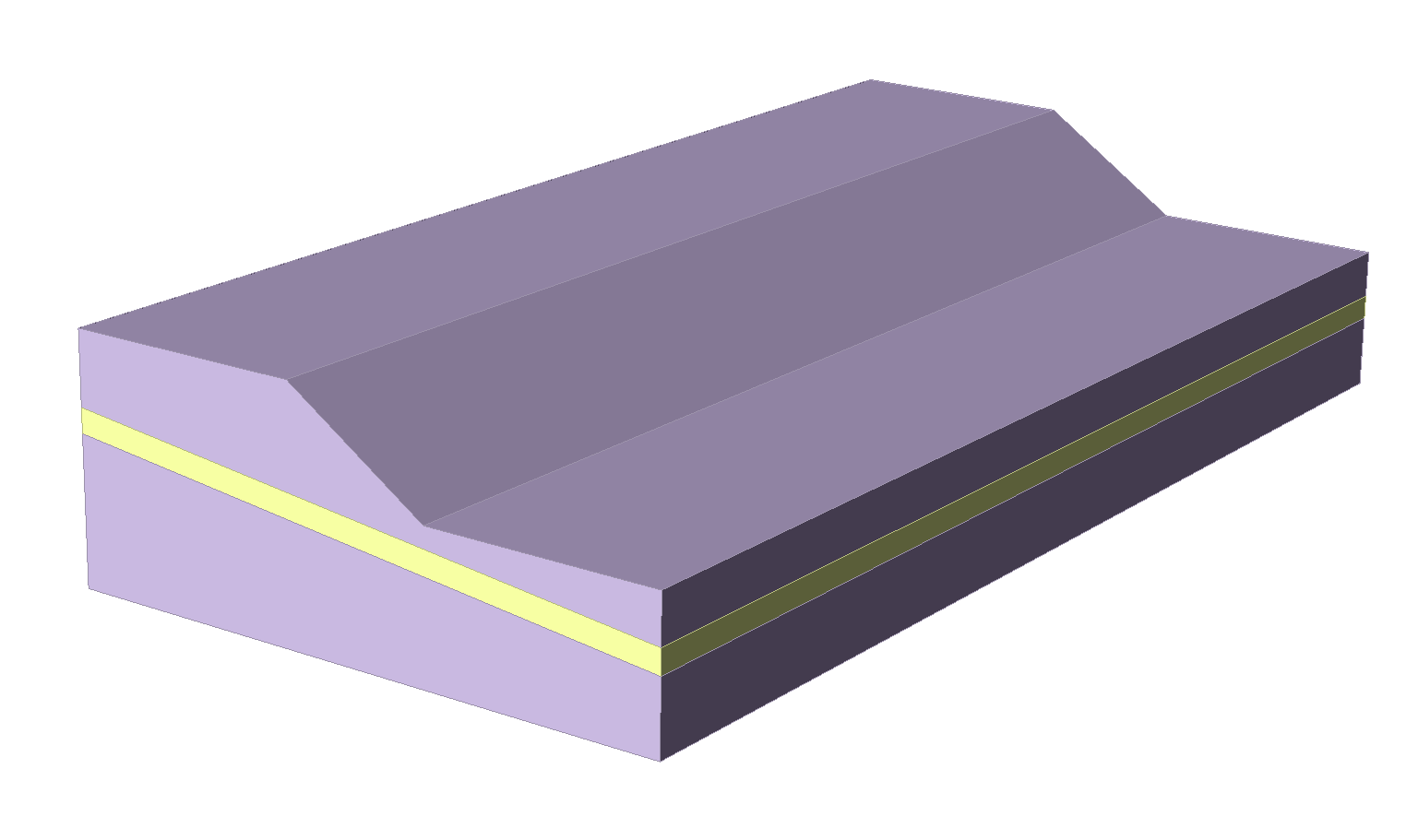
By the end of this tutorial you will be able to create a 3D slope of constant profile with multiple soil regions.
2.0 Slope Wizard Dialog
There are a couple of ways to access the Slope Wizard dialog:
- Select: Geometry > Slope Wizard
 . Alternatively, you can click on the Add 3D Primitives icon on the toolbar to access the Slope Wizard dialog.
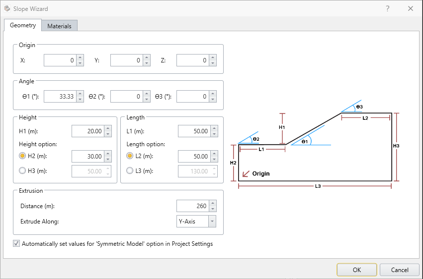
When Slope Wizard is opened, the tab is set to the Geometry tab by default. In this tab, the user can define the geometry parameters (e.g., Origin). Next to this you will find the Materials tab where the user can define soil regions within the 2D slope.
- If you simply select OK in the dialog, leaving all parameters as their default values, an extruded slope model will be created.
We want to define a second material layer and since we cannot make any changes we need to delete the existing geometry first.
- Select the Slope in the Visibility pane on the left.
- Select: Geometry > Clear External

- Delete the Slope directly from the Visibility pane by selecting the garbage can icon
 .
.
2.1 Soil Regions
We will add two material planes to define a weak layer using the Slope Wizard Materials tab.
- Select: Geometry > Slope Wizard
- Navigate to the Materials tab and select the Add Material Plane button twice to add two planes.
- Enter the following values:
| Left Elevation | Right Elevation | Material Above |
|---|---|---|
| 15 | 30 | Material 2 |
| 20 | 35 | Material 1 |
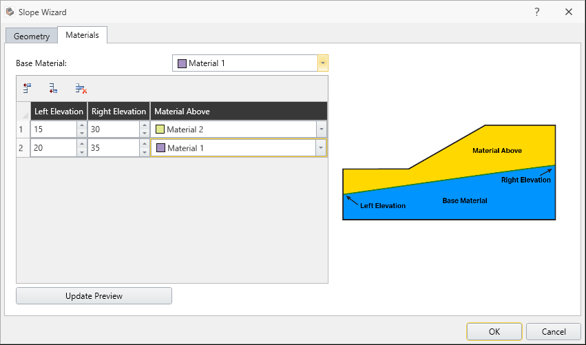
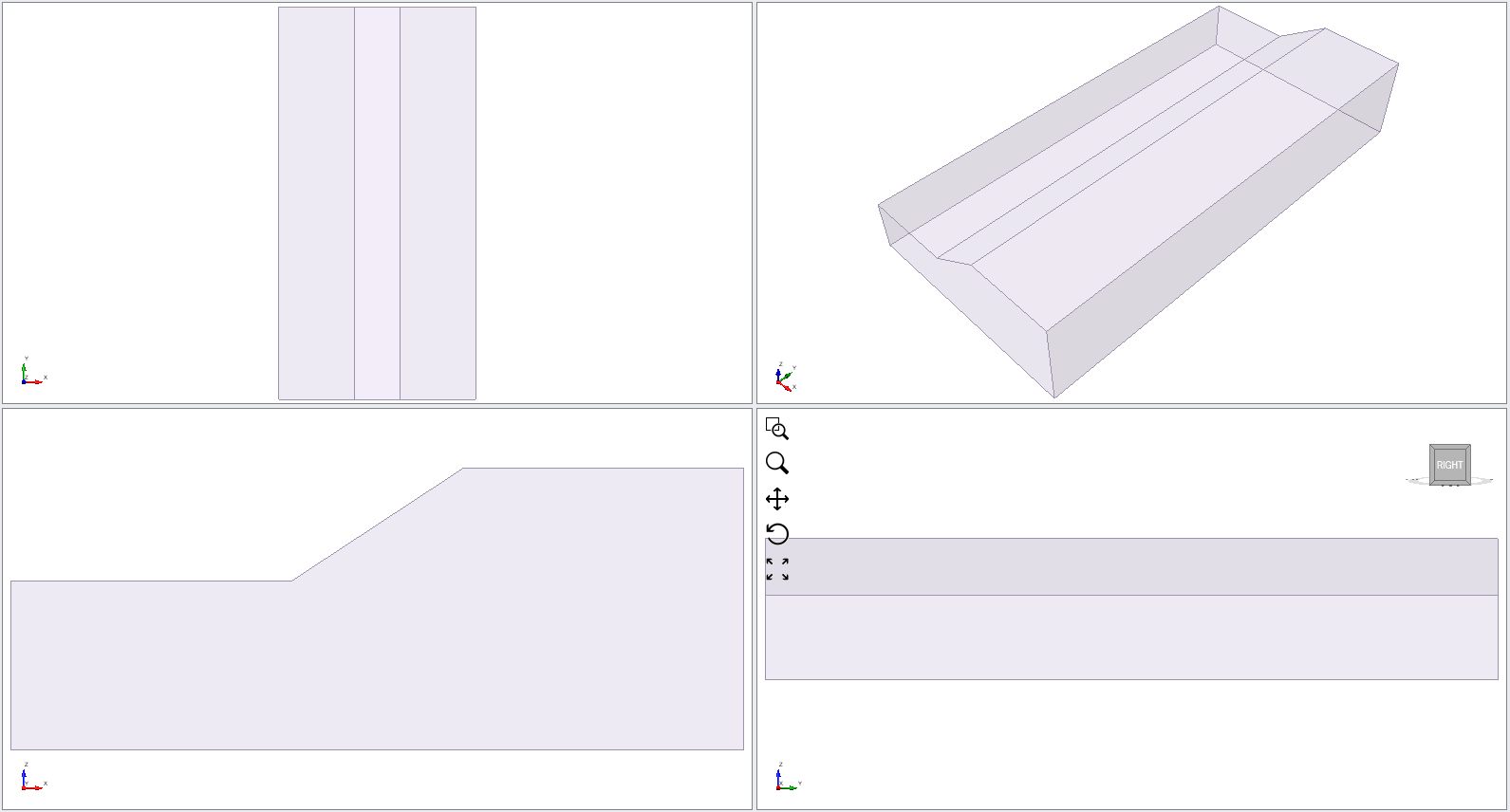
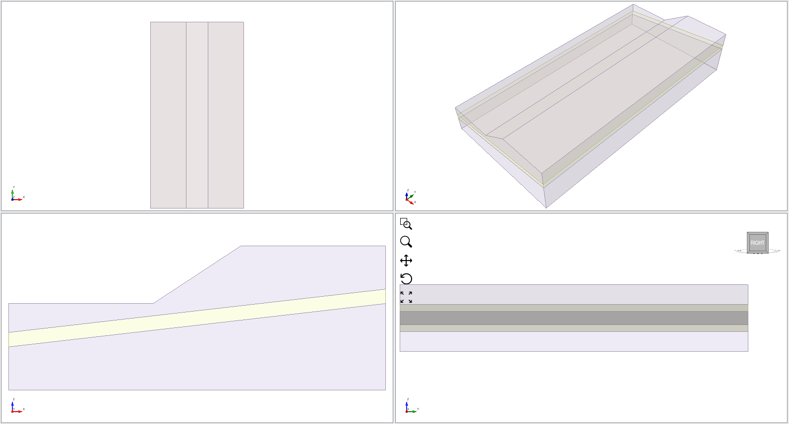
- Click OK.
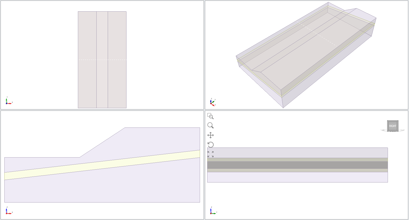
Your screen should look as follows:
3.0 Define Materials
- Select: Materials > Define Materials

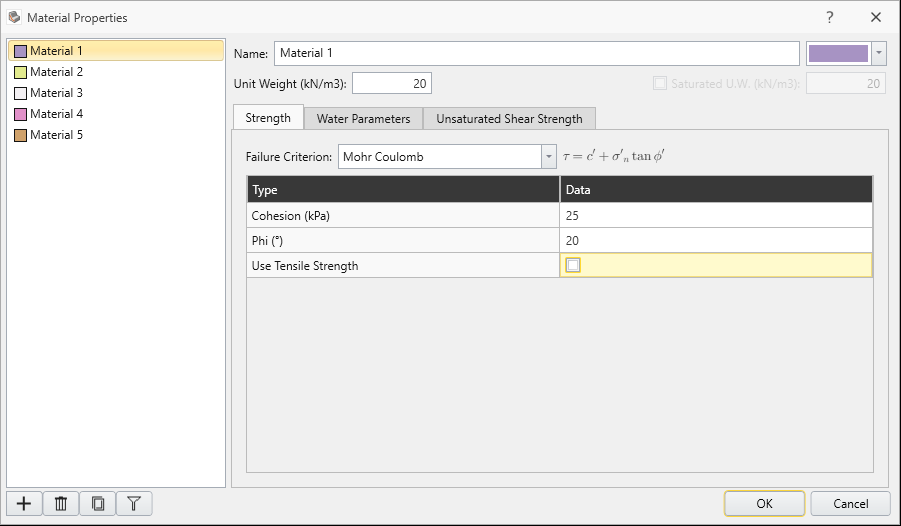
- For Material 1 enter the following:
- Cohesion = 25.
- Phi = 20.
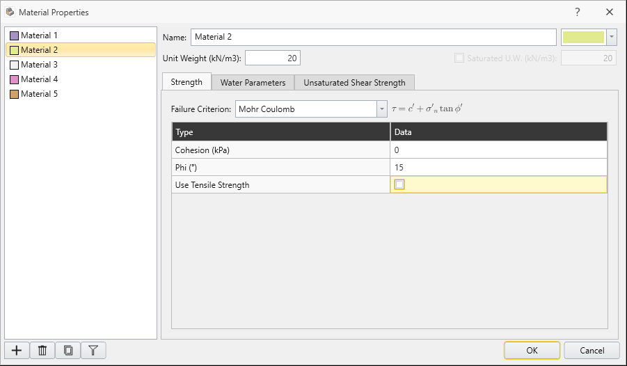
- Define Material 2 as a weak layer. Enter the following:
- Cohesion = 0.
- Phi = 15.
- Select OK.
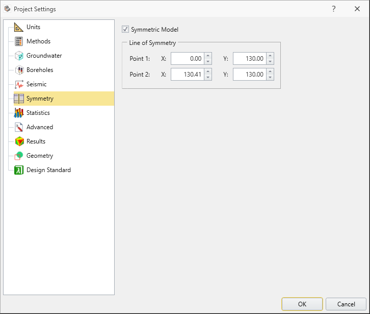
4.0 Symmetry
For the 2D extruded models created by the Slope Wizard, the Symmetry option is turned ON by default. The location of the symmetry plane is also automatically calculated, as you can see if you select Analysis > Project Settings > Symmetry.
5.0 Slip Surfaces
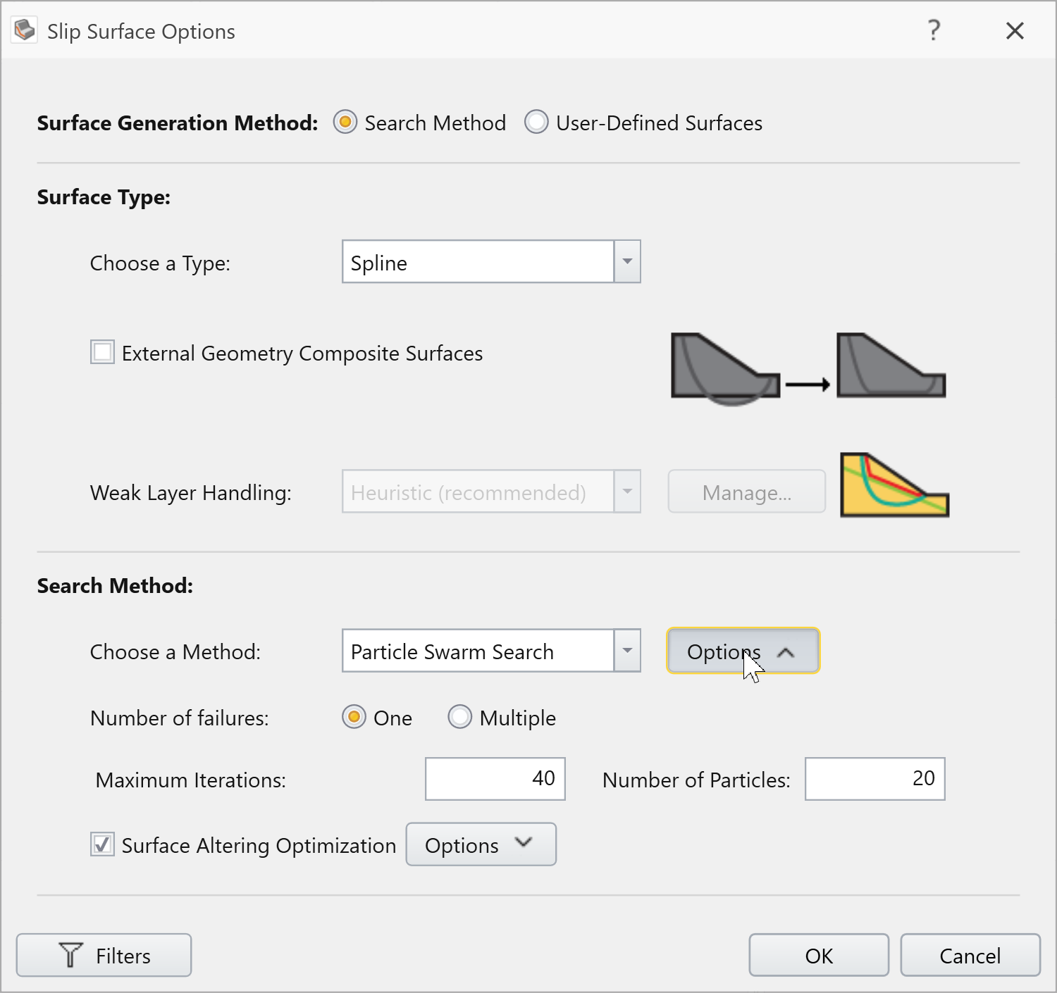
We will use following settings in the Slip Surface dialog:
- Select Surfaces > Slip Surface Options

- Select:
- Surface Generation Method = Search Method
- Surface Type = Spline
- External Geometry Composite Surfaces = OFF
- Search Method = Particle Swarm Search
- Surface Altering Optimization = ON
6.0 Compute
-
Select: Analysis > Compute

7.0 Results
- To view the results, select the Results Workflow tab

- After clicking Show Contour icon
 from the toolbar you should see the Bishop FS about 1.0 with base normal stress contour plot as shown below:
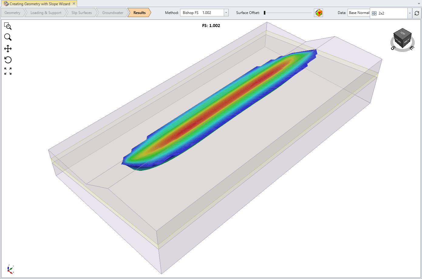
8.0 Conclusion
Now you can experiment with Slope Wizard and try different slope dimensions and material planes to become familiar with its capabilities. Here are the takeaways from this tutorial:
- Slope Wizard is a quick and easy to use tool for geometry creation. It is intended to be a tool for demonstration and teaching purposes.
- If you require more complicated geometry, you will have to build it using the regular geometry creation and editing tools in Slide3.
- After you generate a model using Slope Wizard you CANNOT make any changes.
This concludes the Create Slope Geometry using Slope Wizard Tutorial.