3D Model Clean Up and Creation
1.0 Introduction
This tutorial will run a Limit Equilibrium Analysis on an open pit geometry using Slide3 software. Most of the geometries obtained from mapping and other software can create problems when used in the Slide3 software. It is essential that geometries are cleaned up before being used for 3D modelling purposes. Rocscience provides several tools in Slide3 to simplify or repair problematic geometries. The geometry repair tools are designed to fix different types of issues and not every tool works for every situation. In general, there are three types of fixes that can be done in Slide3:
- Repair tools which fix the defects found in geometries such as holes etc.
- Surface Triangulation tools which fix surface triangulation related issues.
- 3D Boolean (Divide all) tools to fix specific problems.
In this tutorial, the application of all tools mentioned above will be investigated.
The final geometries will be used to build up a model. We will also show how to model a weathering profile in Slide3.
Finished Product:
The finished product of this tutorial can be found in the 3D model clean up and creation.slide3m2 file.
2.0 Open the Model
- Select File > Recent > Tutorials and open 3D model clean up and creation - starting file.
3.0 Project Settings
The basic parameters of the project are defined below. We will set the following Units and Methods in the tutorial.
- Select Analysis > Project Settings
 to open the Project Settings dialog.
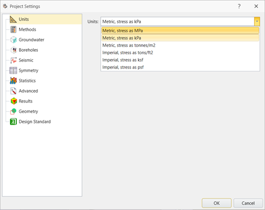
 - In the Units tab, make sure Metric, stress as MPa is selected.
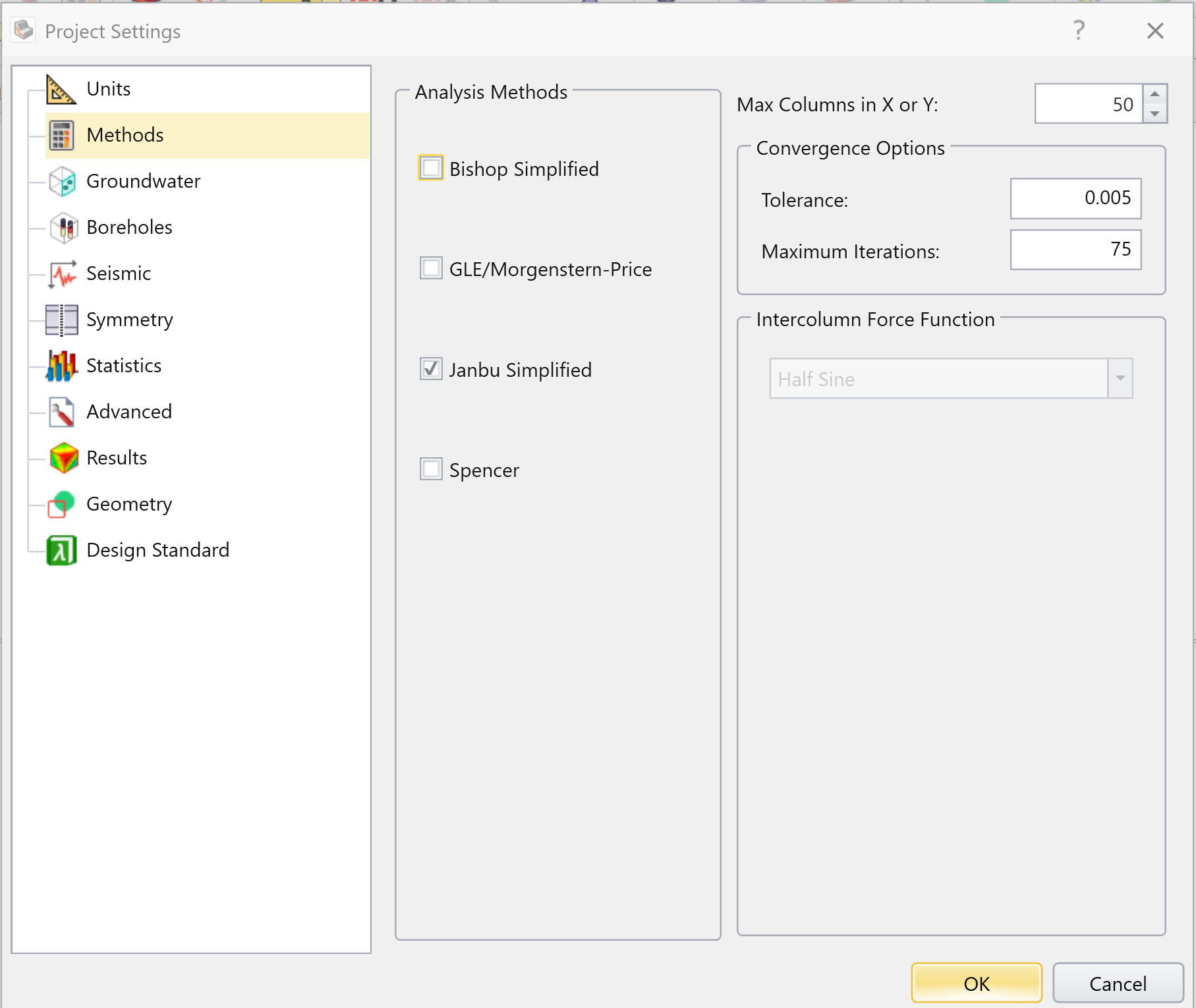
- In the Methods tab, select Janbu Simplified as the Analysis Methods.
- Click OK to save your settings and close the dialog.
4.0 Material Properties
The failure criterion of 'Oxide' is Mohr Coulomb and the strength criterion for the rest of them is Generalized Hoek-Brown.
All materials are already defined and available in the starting file. To view the Material Properties:
- Select Materials > Define Materials

- Click through the pre-defined materials to view.
- When your are done, click OK or Cancel to close the dialog.
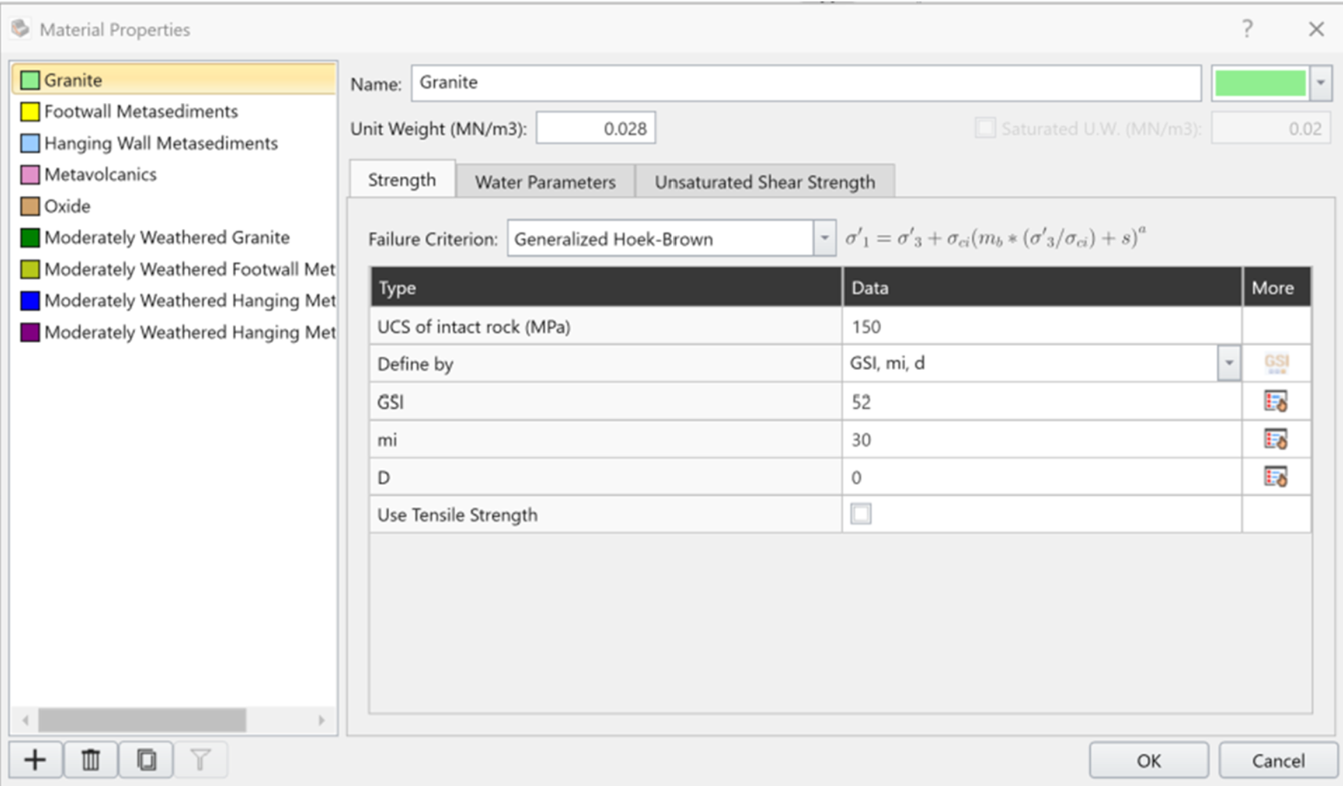
Material properties for the tutorial with Generalized Hoek-Brown criteria:
Material Name |
Unit Weight (MN/m3) |
UCS |
GSI |
mi |
D |
Granite |
0.028 |
150 |
52 |
30 |
0 |
Footwall Metasediments |
0.026 |
80 |
48 |
17 |
0 |
Hanging wall Metasediments |
0.027 |
65 |
55 |
11 |
0 |
Metavolcanics |
0.02 |
120 |
62 |
20 |
0 |
Moderately Weathered Granite |
0.028 |
75 |
38 |
18 |
0 |
Moderately Weathered Footwall Metasediments |
0.026 |
40 |
30 |
10 |
0 |
Moderately Weathered Hanging Metasediments |
0.027 |
30 |
36 |
8 |
0 |
Moderately Weathered Hanging Metavolcanics |
0.02 |
65 |
40 |
15 |
0 |
Material Oxide properties with Mohr-Coulomb criteria:
Material Name |
Unit Weight (MN/m3) |
Unit Weight (MN/m3) |
Phi (o) |
Oxide |
0.020 |
0.020 |
30 |
5.0 Geometry Clean up
We will begin the geometric components of the tutorial with the ‘open pit with topo’ file.
To import geometry into Slide3:
- Select Geometry > Import/Export > Import Geometry.
- Select the ‘Open Pit Shell and Topo’ file (located in the same folder as the starting file) and click Open. The Import Geometry dialog will appear.

- Tick the All Geometry checkbox, then click Post Processing (at the bottom of the dialog).

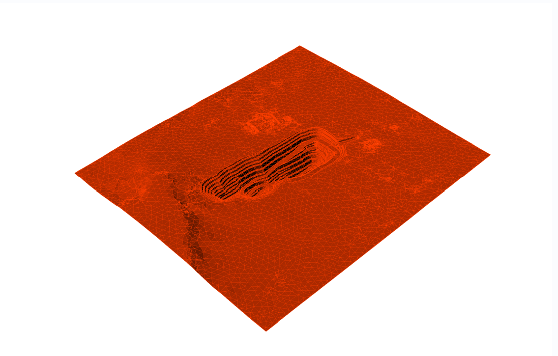
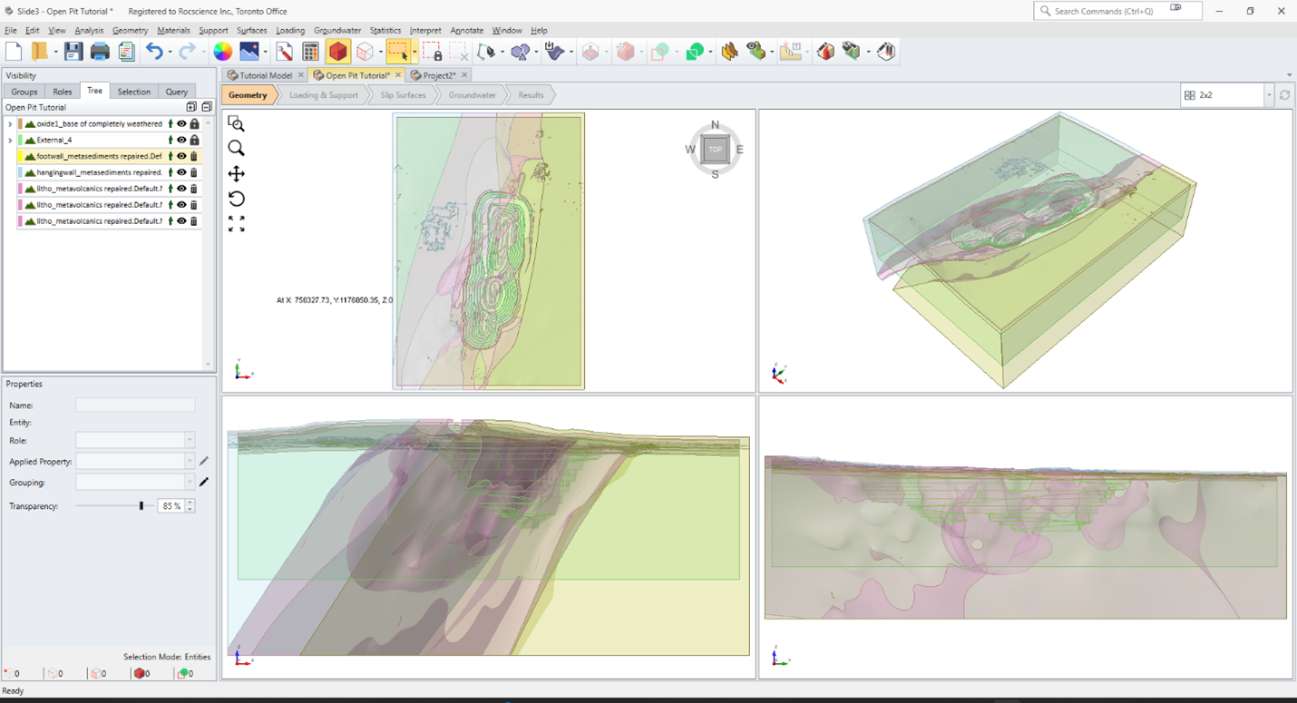
- Click Done to import the geometry. The successfully imported geometry is shown below.

6.0 Repair Geometry
Slide3 has a Repair tool that can be used during the import geometry process. However, it is also accessible later on in the modelling process from the Geometry menu. We recommend that you apply this tool only after successfully importing the surface. Repair generally fixes surfaces very well. Its dialog shows defect counts found for the different error categories.
- Repair can distort geometries after fixing defects. Use it with caution. You may have to change its default settings (as will be done in this tutorial) to improve results.
- To perform any function on an entity, it must be selected first.
The first step of Repair is normally re-triangulation, but looking at View > Show all edges, the triangulation seems fine. It is small enough, uniform, and the same size.
- Select the imported geometry in the Visibility Tree (or you can select the entity in the viewport with your mouse using the Select Entity
 tool). In the menu select Geometry > Repair Tools > Repair.
The dialog shows that the ‘Open Pit Shell and Topo’ surface has near-degenerate triangles, holes, and non-manifolds.
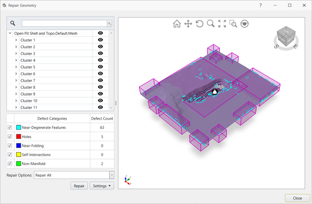
- Leave the default Repair Option as Repair All. Click the Repair button and the defects will be fixed.
- Close the dialog.
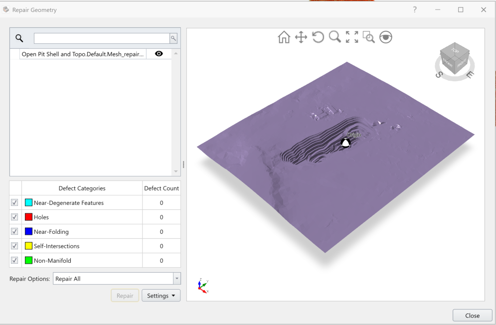
We can now create a volume from the repaired surface.
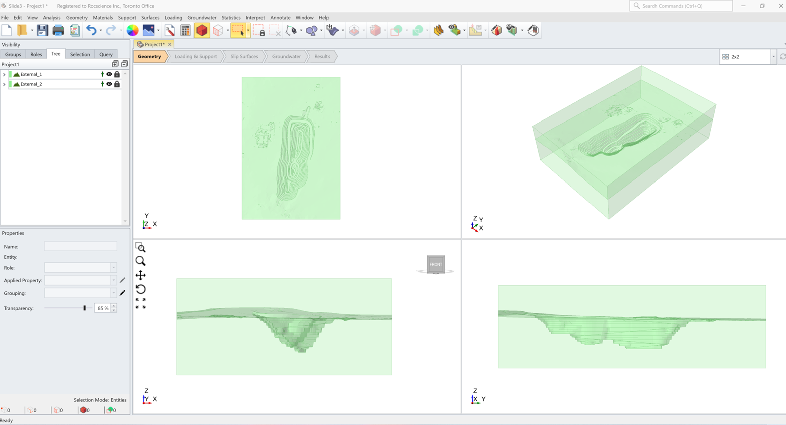
7.0 Creating an External Volume from the Open Pit Surface
We will use the ‘External Box’ method to create our model external boundaries with the surface.
Go to Geometry > Create External Box. The external box is defined by ‘Two corners. Enter the coordinate values given in the table below. And click ‘OK’.
X
Y
Z
First Corner
757030
1,176,385
-65
Second Corner
758,025
1,177,835
380
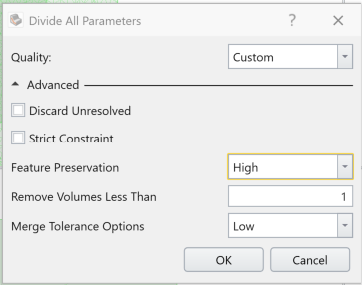
The External box dimensions were chosen so that the box does not extend beyond the lithology geometry boundaries.- Go to Geometry > 3D Boolean > Divide All Geometry, and in the ‘Divide All Geometries’ dialog, click on Advanced, and change ‘Feature Preservation’ to ‘High’. Then, Click OK.
 You can also turn on the ‘Strict Constraint’ option. This can significantly slow down the Divide All process if there are several tiny gaps between 3D geometries. This feature can eliminate these gaps with an iterative process, but that can run for long.
At the end of ‘Divide All’, the external volume is divided into an upper and bottom volumes. The bottom volume (with the pit) is the only one needed for the model. We will therefore delete the upper external volume.
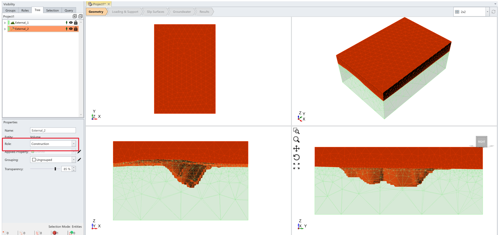
- Select the upper section, and in the Properties pane (below the Visibility pane), change its Role from Geology to Construction as demonstrated in the image below.By setting the role of a volume, resulting from Divide All, to ‘Construction’ allows it to be discarded from a volume and does not create holes. It also makes the volume indivisible in subsequent Divide All operations until the role is reset to Geology.
Construction pieces are the pieces that will be ignored in the analysis process. - With the upper section still selected, select Geometry > Discard selected Construction Geometry. This will delete the upper external volume.
 Alternatively, you can export the lower external volume to a 3D file and import it into a new Slide3 project. This approach will eliminate geometry history and reduce the size of models.
 - If another material is assigned to the remaining Open pit external volume, assign Granite to it. Select the entity from the Visibility tree and select Granite from the Applied Property drop down (in the Property pane).All lithologies used for this tutorial were listed in Table 1 above and previously entered in the material property dialog.
We will now repair the geometry of the Completely Weathered Surface and create a volume out of it. We will also clean up the 'Litho Metavolcanics' volume (All the other volumes have already been repaired).
8.0 Repair of the Completely Weathered Oxide Surface
- Select Geometry > Import/Export > Import Geometry and import the oxide 1_ base of completely weathered file into the model (or a new Slide3 project) to repair it.
Note that, after import, the Entity field in the properties pane shows the geometry to be a Surface.
- Click on Find and Repair Defects, you can see it has several near-degenerate triangles and holes.

- Click the Repair button and you will see all defects will be fixed.
- Click Close and then Done.
- With the surface selected in the Visibility Tree, select Geometry > Extrude/Sweep/Loft Tools>Extrude in the menu to open the Extrude dialog.
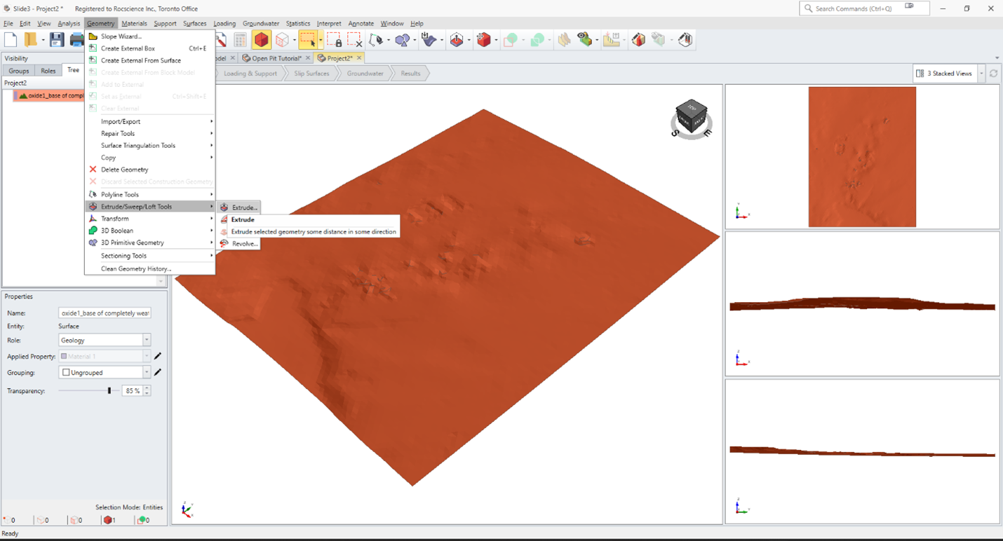
- Under Direction, click Z Axis and enter Depth = 20.
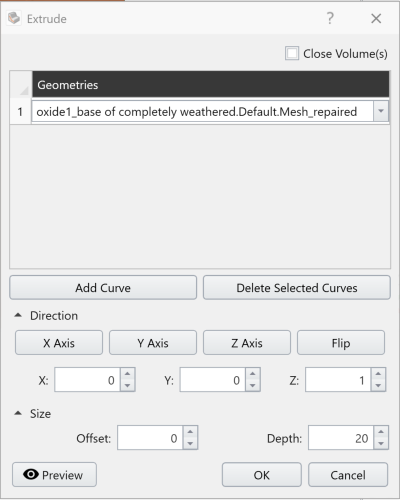
- Click OK to extrude the surface 20 units upwards (i.e., along the positive z-direction). The Entity type now changes to Volume in the properties pane.
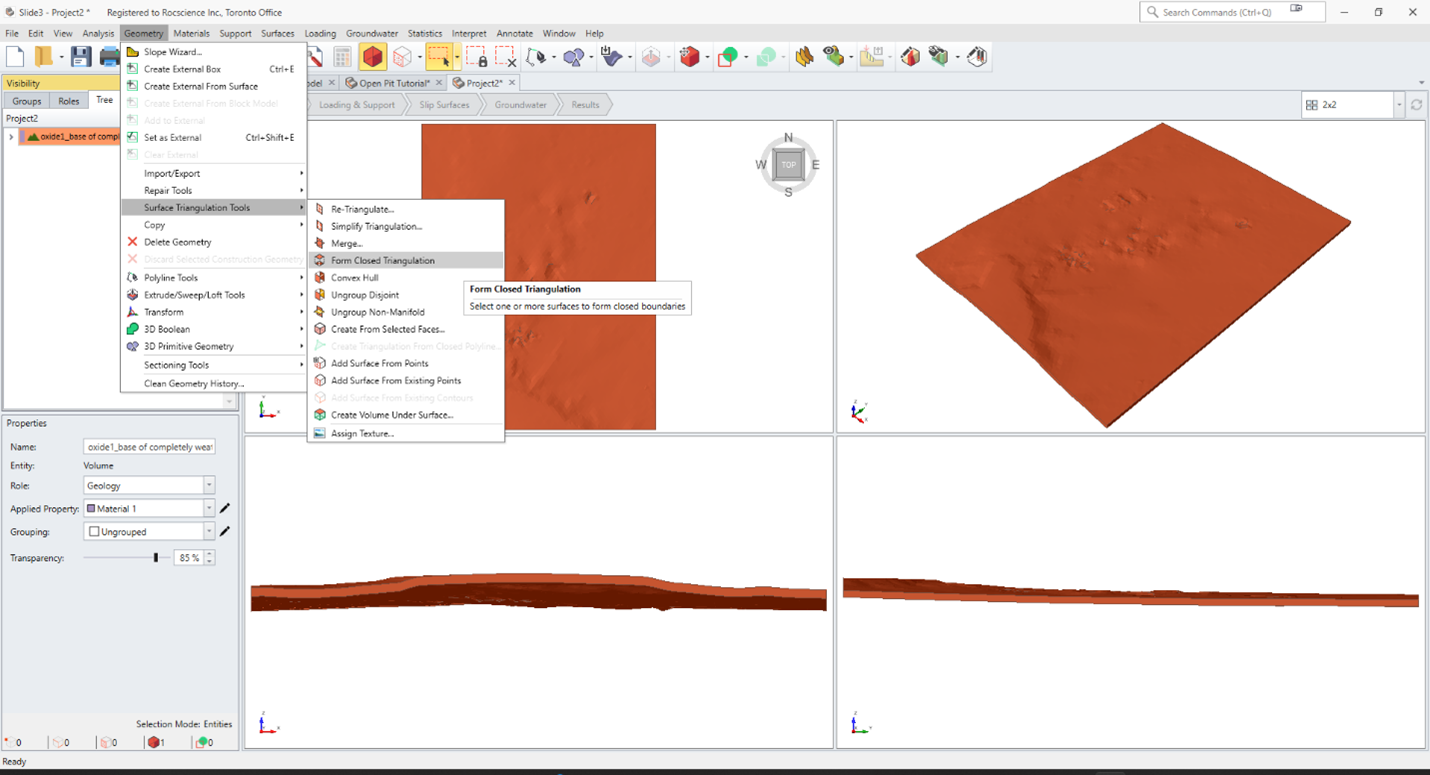
- With the volume selected, select Geometry > Surface Triangulation Tools > Form Closed Triangulation in the menu. This function takes a selected entity and attempts to form a closed volume out of it if the object is not watertight. It also ensures that the normal to the triangles forming a volume consistently point outwards.Whenever there is volume in models, we recommend performing Form Closed Triangulation to ensure that the volume is totally watertight.
- If you imported this surface into a new project and repaired it there, now you need to export it as a dxf file to import it into the main model later in the section 10.0 Model Setup.
9.0 Repair of Litho Metavolcanic Volume
- Open another Slide3 project. Select Geometry > Import/Export > Import Geometry and import the ‘litho metavolcanic’ file. Once imported into Slide3, you will notice that the object comprises different sub-volumes that are all grouped under one node in the Visibility Tree. This situation can be problematic in 3D modelling.
- First, re-triangulate it. Select Geometry > Surface Triangulation Tools > Re-Triangulate in the menu, leave it as the default and press OK.
- Select Geometry > Surface Triangulation Tools > Ungroup Disjoint. This function will separate out the component volumes. To simplify the tutorial geometry, we will only use lithological volumes greater than 50,000 for the model.
- In the Visibility pane, select the Query tab. Click + Press to Query model. Apply the following Query criterion for the search query terms:
- Geometry
- Volume
- ‘<’ (less than) Boolean operator
- Enter a value of 50 000.
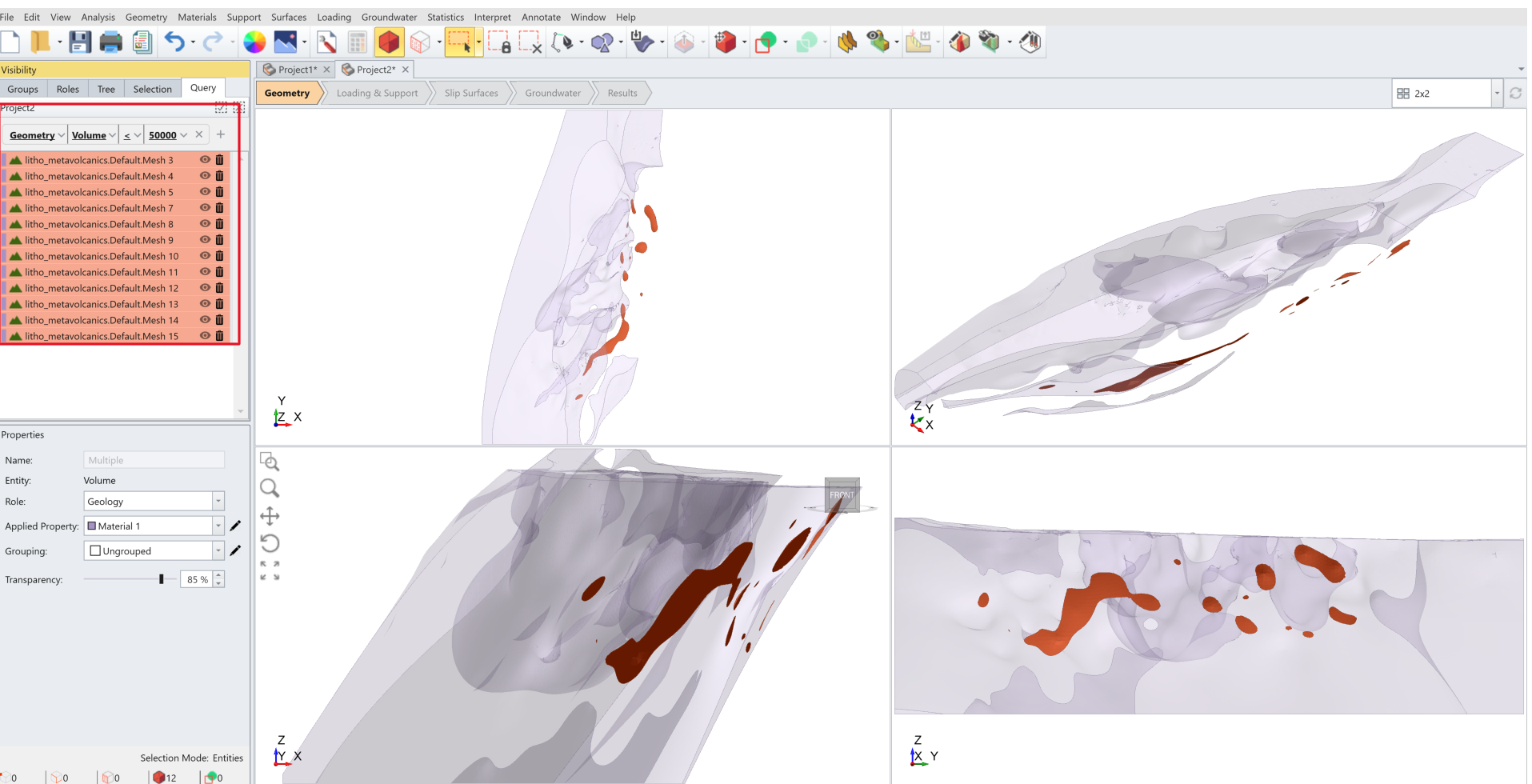
- Select the queried entities from the Visibility Tree, and change their Role to Construction. Then remove them by selecting Geometry > Discard Selected Construction Geometry.
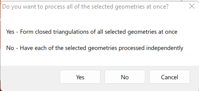
- Remove search query term, then select three remaining volumes from the Visibility tree. Select Geometry > Surface Triangulation Tools > Form Closed Triangulation. Press 'No' to have each of the selected geometries processed independently.
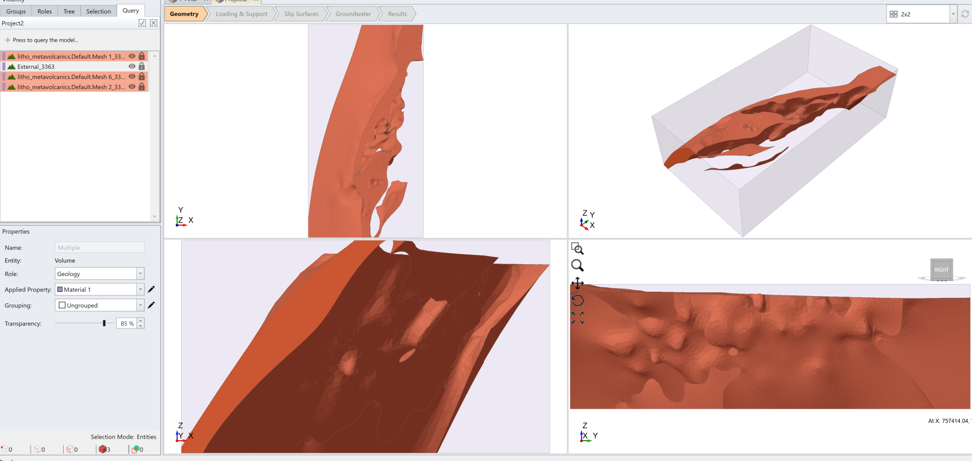
- Select Geometry > Create External Box, leave external box parameters at their default and press OK.
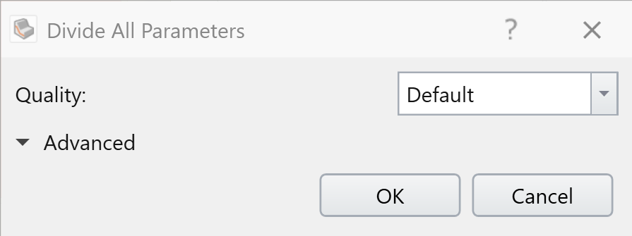
- Then select Geometry > 3D Boolean > Divide All Geometry and and in the Divide All Parameters dialog, change Quality to High, and then, press Ok.
- Now select these three volumes and select Geometry > Import/Export > Export Geometry to export them to a file named ‘litho metavolcanic repaired’.
We will import the lithologies into the Slide3 project with the ‘Open pit with Topo’ external volume .
The hanging and footwall metasediments volumes were already repaired for the tutorial.
10.0 Model Setup
- If you repaired the 'oxide 1_base of completely weathered repaired volume' separately in a new project, import it into the main model consists of the created external volume from 'Open pit with Topo'. Otherwise, it is already included in the main model.
- We will assign it the ‘oxide’ material property in the Properties pane. To do so, select the object and, in the ‘Applied Property’ field, click on the drop down arrow and select ‘oxide’ from the list.
- To include the imported geometry in the model, select Geometry > 3D Boolean > Divide All Geometry.
After ‘Divide All’, the completely weathered profile is included in the model (a padlock beside the entity under the Visibility Tree.

- Next, import the following repaired lithologies: Footwall metasediments, Hanging wall metasediments, and litho metavolcanic repaired.

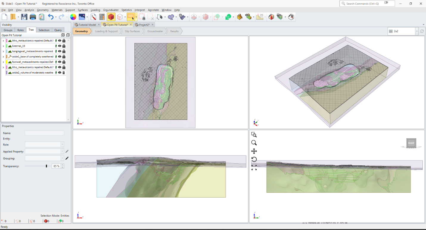
Assign the appropriate material property to each imported geometry through the Applied Property field, as shown in the table and image below.
Geometry Property to Apply
litho metavolcanic repaired
Metavolcanics
footwall metasediments repaired
Footwall Metasediments
hangingwall metasediments repaired
Hanging Wall Metasediments
- Select the oxide 1_ base of completely weathered repaired volume and change its Role from Geology to Construction. This will prevent it from being divided again as described earlier. Once set as Construction, the completely weathered geology will now be shown with a hatched pattern.
- To incorporate the new geologies into the model, run the Divide All Geometry operation with considering Default for the Quality option.
- Select all entities from the Visibility pane and then, collapse material boundaries by Geometry > Repair Tools > Collapse Material Boundaries and remove volumes less than 50000 in Geometry > Repair Tools > Collapse Small Volumes:
- Finally, import the last geological volume, 'oxide2_volume of moderately weathered'. If you go to Geometry > Repair Tools, you will see there are only three Near-Degenerate Features which will be repaired later in the process of Divide All.
- Select this entity in the Visibility Tree and apply the following actions in the Properties pane:
- Set the Applied Property to Derive – this setting implies that sub-volumes of this entity resulting from Divide All will acquire the properties of the volumes in the model that they intersect.
- Set the Grouping property field to Group 1 – this setting will make it easy to identify all lithologies that result from intersections with the moderately weathered volume. We need this to readily set the moderately weathered granite, footwall metasediments, hanging wall metasediments and litho metavolcanic volumes.

- Run Divide All again.
- Collapse small volumes again by going to Geometry > Repair Tools > Collapse Small Volumes and set the Remove Volumes Less than (m3) to 50000.
- Once the process is done, click on the Group tab in the Visibility Pane and select Group 1 to see the list of the moderately weathered sub-volumes.
We will now set the properties of the moderately weathered sub-volumes to their respective lithologies. Select the first oxide2 volume of Group 1; it has the Hanging Wall Metasediments property. Change this property to Moderately Weathered Hanging Wall Metasediments, and do the same for the materials of the remaining oxide2 entities in Group 1 to properties shown in the following table:
Material Property After Divide All Property to Apply
Granite
Moderately Weathered Granite
Footwall Metasediment
Moderately Weathered Footwall Metasediments
Metavolcanic
Moderately Weathered Metavolcanic
- Finally, select the oxide 1_ base of completely weathered repaired volume and change its Role back to Geology.
Now we will import a water table and include it in our slope stability analysis .
11.0 Importing the Water Table
- Import the file named Water Table 2.
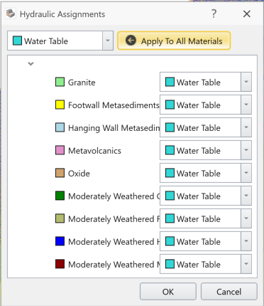
- Select this imported geometry and go to Groundwater > Add Water Surface. This opens the Add Water Surface dialog shown below.

- Click OK to close the dialog. The Hydraulic Assignments dialog pops up.
- Click Apply to All Materials and then OK to close the dialog.
12.0 Search Method
We will use the Ellipsoid failure surface shape and the Particle Swarm Search method to determine the critical slip surface.
- Go to Surfaces > Slip Surface Options to open the dialog below.
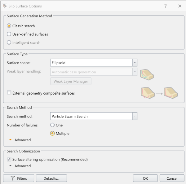
- Set the following:
- Type = Ellipsoid
- Method = Particle Swarm Search
- Number of failures = Multiple
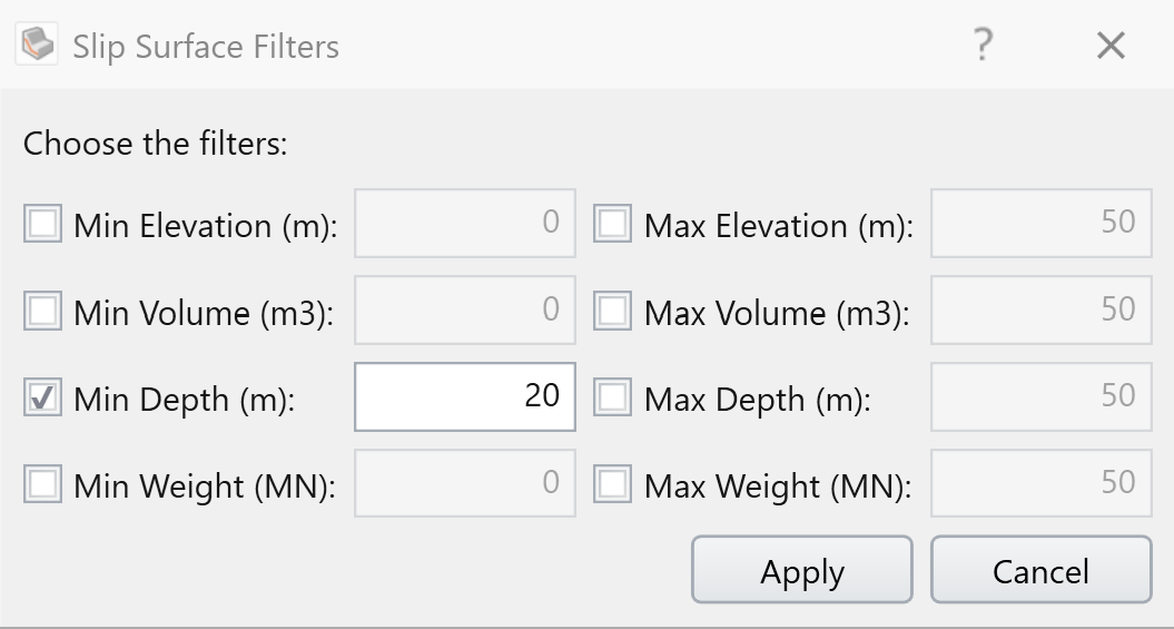
- Click on Filters and set the Min Depth to 20m.
- Click OK to save the settings and close dialog.
We are now ready to run the slope stability analysis.
13.0 Computation and Interpretation
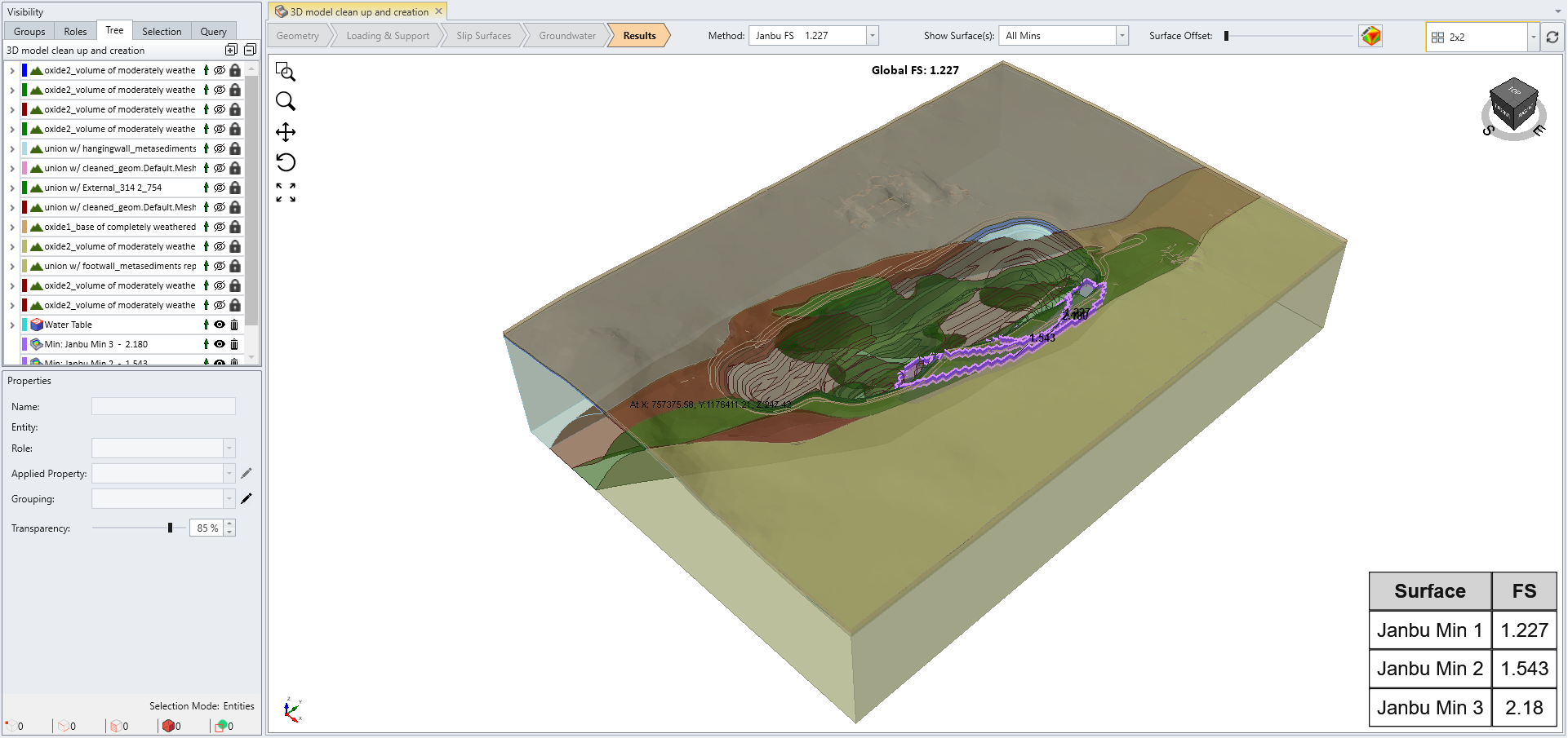
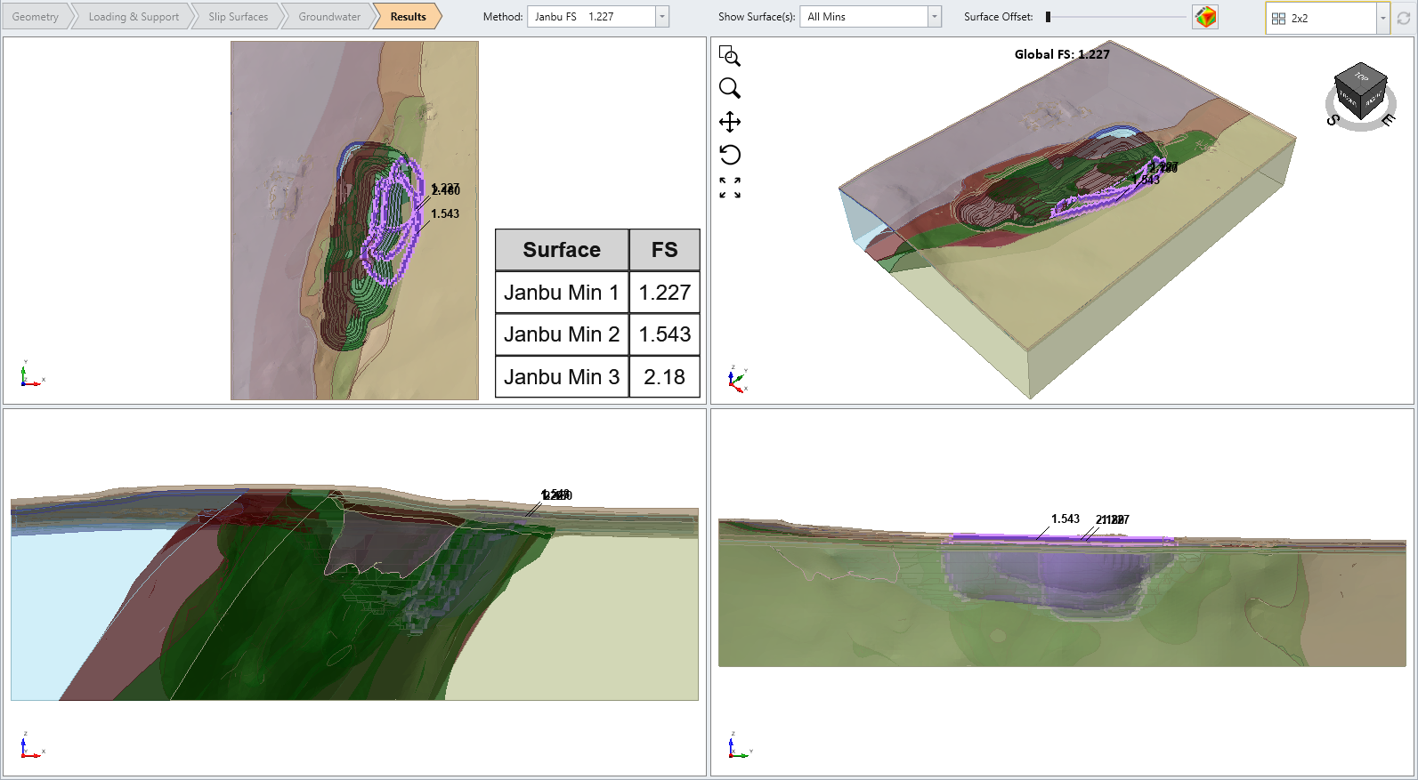
- Select Analysis > Compute to run the model.
- Click the Results workflow tab to see the slip surfaces and their safety factors once the computations are done.
This concludes the tutorial.