Generalized Anisotropy – Exporting from Slide3 to Slide2
1.0 Introduction
This tutorial will go over the process of exporting 3D anisotropic surfaces from Slide3 to Slide2 and what you need to know in the process.
NOTE: For a video introduction to this feature, see the webinar snippet here:
2.0 Model Review
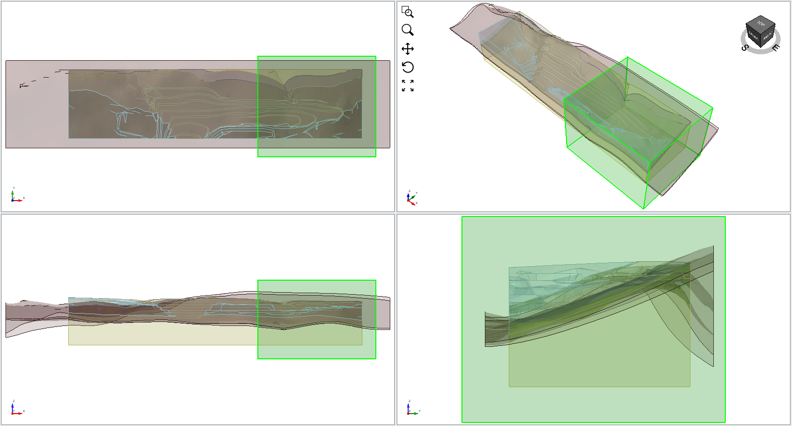
- In Slide3, select File > Recent > Tutorials Folder in the menu and open the file Anisotropy - Slide3 to Slide2. The model will look as shown.
Select Materials > Define Materials . Notice that materials GA1 and GA2 are generalized anisotropic material types which follow anisotropic surfaces.
 - In material GA1 click More
 (pencil icon) to view the strength function. The material follows an anisotropic surface as shown:
- Click Cancel.
- Play around with the model to locate the generalized anisotropic materials and their corresponding anisotropic surfaces.
3.0 3D Results
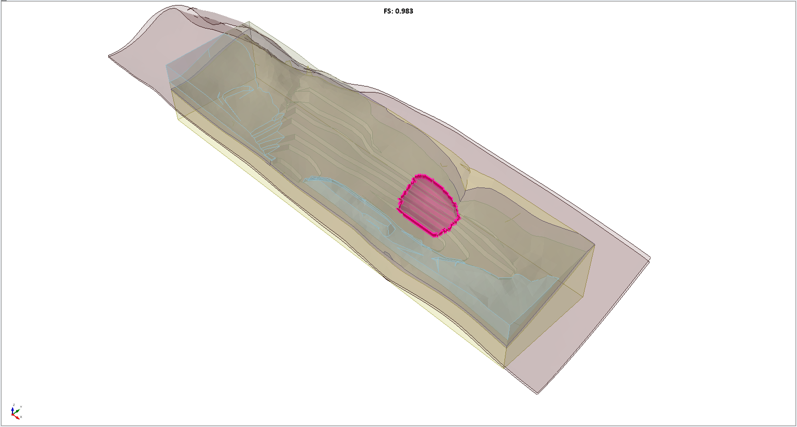
- Select Analysis > Compute
 or click on the Compute icon in the toolbar.
 - Select the Results tab.
The factor of safety is just below 1 as shown:
4.0 Export to Slide2
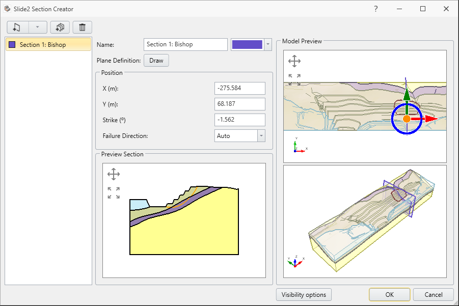
We will now create the Slide2 section through the global minimums for export.
- Select the Create 2D Sections through Global Minimums option from the Interpret menu.
- The Slide2 Section creator dialog will appear, with the newly created Slide2 sections.
- Select Analysis > Slide2 Integration > Compute/Export to Slide2
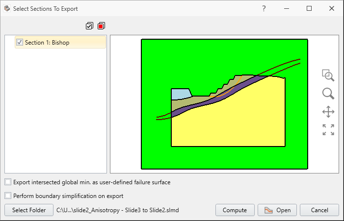
- Ensure Section 1: Bishop is selected. Click Open.
- Your Slide2 model will look as shown:
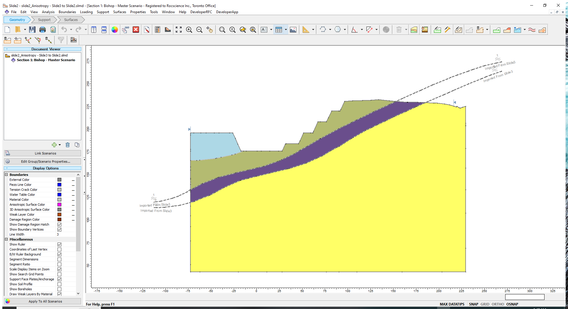
Notice that the anisotropic surfaces are labeled as “Imported from Slide3.” We will now review the material parameters.
- Select Properties > Define Materials

- Click on GA1.

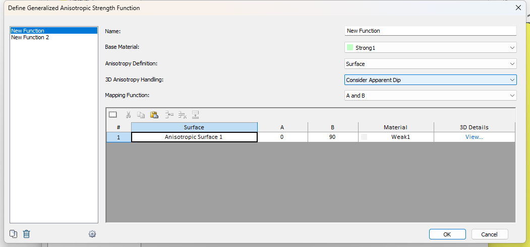
Notice that the Strength Type is Generalized Anisotropic and the Input Type is Imported from Slide3. This Input Type will only be available for models that were exported from Slide3.
- Click on the Edit (pencil icon) next to the function. The function dialog looks the same as it did in Slide3 with the following differences:
- There is a 3D Anisotropy Handling option.
- There is a 3D Details column.
- First click View in the 3D Details column.

We can see the strike of the 2D section we defined in Slide3, and the 3D dip and dip direction of the anisotropic plane at each segment along the anisotropic surface.
- Click OK.
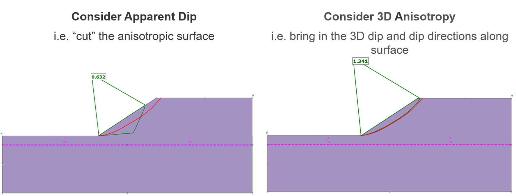
Now let’s explore the 3D Anisotropy Handling option. There are two options in the dropdown. They are explained below:
- Consider Apparent Dip: cut the anisotropic surface at the location of the Slide2 section. This is a pure 2D analysis where the 2D section doesn’t know about the 3D anisotropy around it.
- Consider 3D Anisotropy: since we are taking a 2D section inside of our 3D model, we want the 2D model to be aware of the true 3D anisotropic surface so that our 3D and 2D results are comparable.
5.0 2D Results
5.1 Consider Apparent Dip
We will first try the pure 2D analysis.
- Set the 3D Anisotropy Handling option to Consider Apparent Dip.
- Click OK.
- Click on GA2 in the dialog and click the Edit (pencil icon).
- Set the 3D Anisotropy Handling option to Consider Apparent Dip.
- Click OK in this dialog and in the Material Properties dialog.
- Select Analysis > Compute or click on the Compute in the toolbar.
- Select Analysis > Interpret
 to launch the Slide2 Interpreter.

The factor of safety in Slide2 is very similar to the one in Slide3. As well the slip surface in Slide2 (in green) is very similar to the Slide3 surface (in red).
By selecting Consider Apparent Dip, this analysis assumes that the anisotropic surfaces are purely 2D and are simply the ones we see on the screen. They are equivalent to the regular 2D anisotropic surface.
5.2 Consider 3D Anisotropy
Now let’s try to compute while considering the 3D orientations.
- Select Analysis > Modeler
 to return to the Slide2 Modeler.
 - Select Properties > Define Materials
- This time, set 3D Anisotropic Handling to Consider 3D Anisotropy for both GA1 and GA2.

- Click OK in both dialogs.
- Select Analysis > Compute or click on the Compute icon in the toolbar.
- Select Analysis > Interpret
The results will look as shown:

By selecting Consider 3D Anisotropy, this analysis is using the dip and dip direction at each segment along the anisotropic surfaces, so that we can imagine this as a 2D section with two 3D anisotropic surfaces.
6.0 Discussion
The results between the Consider 3D Anisotropy and Consider Apparent Dip are almost identical in both slip surface shape and factor of safety. This is because the anisotropic surfaces are approximately extruded along the x axis in the Slide3 model. In other words, the dip direction of the anisotropic planes is roughly the same as the dip direction of the Slide2 section. In this case, these methods will give very similar results.
6.1 Which method is correct?
Unfortunately, there is no black-and-white answer. No matter how you look at it, you are trying to represent a 3D object on a 2D plane. There’s no “correct” way of doing it. You need an assumption that’s best for your model. As a user, you must tell the software the type of analysis you want to compute:
- Consider Apparent Dip: cut the anisotropic surface at the location of the Slide2 section. This is a pure 2D analysis where the 2D section doesn’t know about the 3D anisotropy around it.
- Consider 3D Anisotropy: since we are taking a 2D section inside of our 3D model, we want the 2D model to be aware of the true 3D anisotropic surface so that our 3D and 2D results are comparable.
6.2 In which cases will the results be different?
When the direction of anisotropy is not similar to the direction of failure and the direction of the 2D section, the results will change drastically. For an example, see the webinar clip at the link: https://youtu.be/AKirBTmV0DM?t=2007