Guide to Divide All
1.0 Introduction
Divide All is an essential function to model creation for most models. Analogues to subdividing external boundaries to create material regions in enclosed polylines in our 2D software, Divide All splits 3D external volume to smaller pieces, for material, support or loading assignments. If a new piece of geometry is imported or created for the purpose of defining new properties of a subspace within external volume, you must select Divide All to intersect the geometry with the current state of external volume.
The function has received major upgrades to handle highly complex 3D geometries.
Topics Covered in this Tutorial:
- Model creation with an external volume and a set of cutting surfaces.
- Collapse small volumes after divide.
- Introduction to the concept of sequential divides.
- Utilizing Construction role to choose what not to divide.
- Utilizing Union to glue unintended splits.
2.0 Model Creation with an External Volume and a Set of Cutting Surfaces
- From the Slide3 main menu, select File > Recent > Tutorials and open the file Guide To New Divide All - starting file.
This file contains one external volume, two cutting surfaces (Surface 1 and 2) and Material Region, as shown below.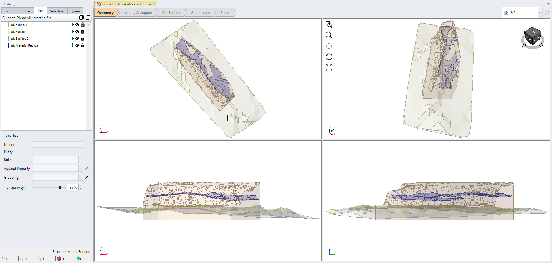
The Visibility pane on the left side of program lists all available items in the current project. Notice the External geometry exhibits a lock icon ![]() whereas the other three geometries do not. This indicates that the three geometries are not intersected with the external boundary yet.
whereas the other three geometries do not. This indicates that the three geometries are not intersected with the external boundary yet.
Now we want to divide all geometries.
- Select Geometry > 3D Boolean > Divide All Geometry or select the Divide All
 icon from toolbar.
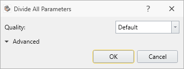
Divide All Parameters dialog helps users to fine tune the behavior of Divide All function. Setting Quality to Default option is suitable for a wide range of models in general, however, there are cases where changing the setting is required to successfully intersect every geometry with external boundary. For more detail about each option under Divide All Parameters, please refer to Divide / Un-Divide All Geometry.
- Select OK to begin dividing.
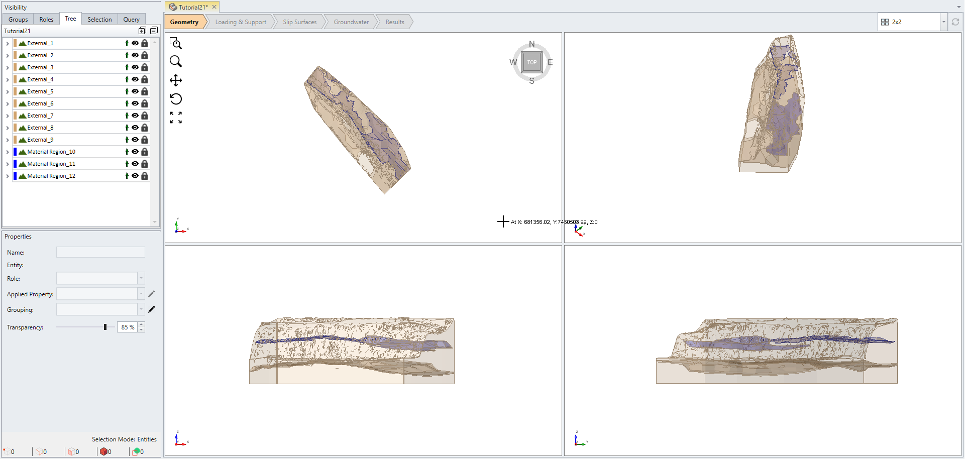
Notice now every item in the visibility tree has a lock in front of it. This indicates that all geometries have successfully intersected with external volume.
2.1 Collapse Small Volumes After Divide
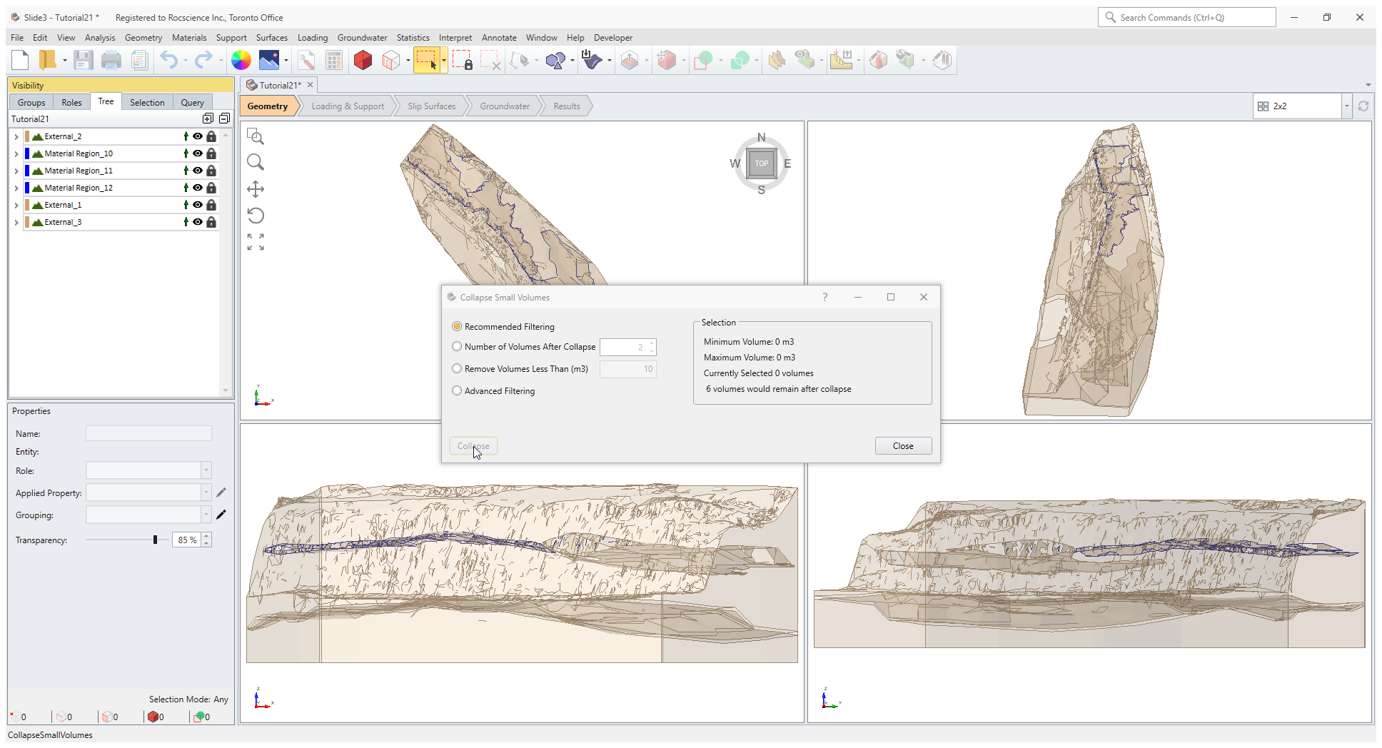
After using Divide All with complex geometry, you may find that small geometry pieces have been created.
- Select External 4 to 9 under the Visibility pane and change the Transparency under the Properties pane to 100%. You can see that these small pieces were generated.
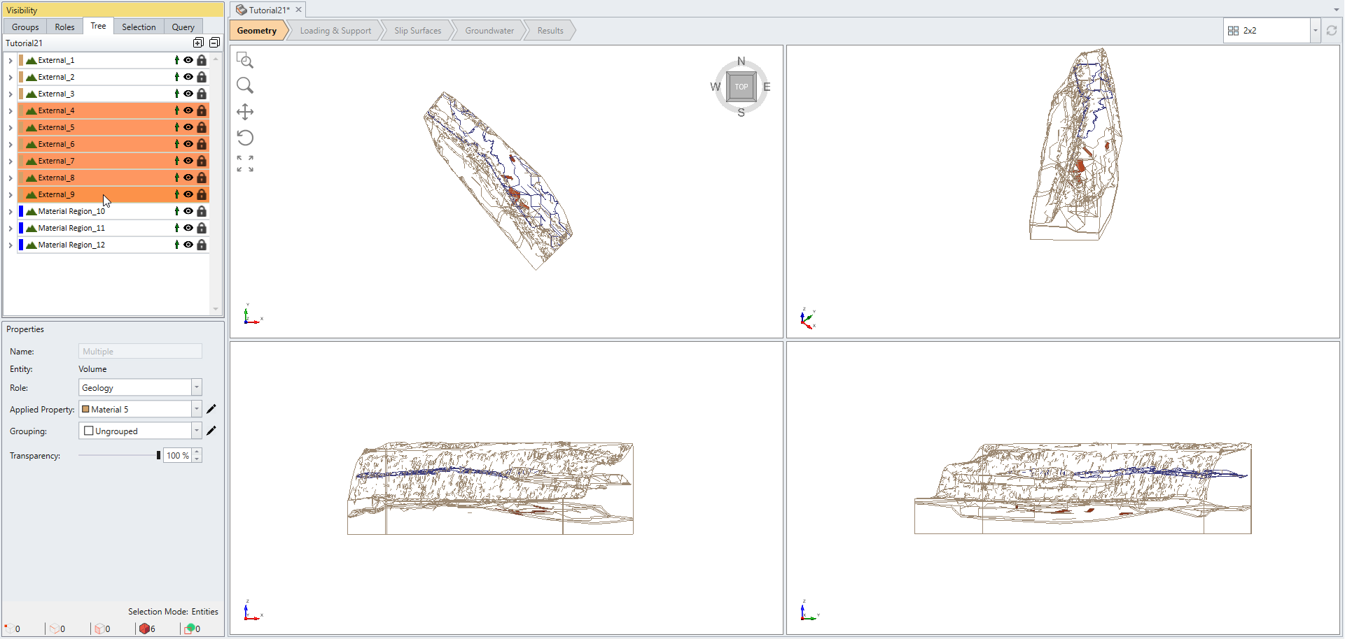
In this example, the two cutting surfaces happen to intersect and thus form small volumes as highlighted in orange.
The improved Divide All function is capable of resolving difficult intersections between geometries.
The small volumes could be undesired features in the model. The Collapse Small Volumes function is handy for removing many of these small geometries.
To Collapse the Small Volumes:
- Deselect the external layers (Edit > Clear Selection).
- Select Geometry > Repair Tools > Collapse Small Volumes
The default option in the Collapse Small Volumes dialog is Recommended Filtering, which automatically finds and suggests which volumes to collapse.
Note: It is recommended to preview what has been determined as small volume by any filtering option.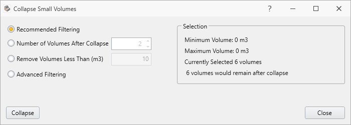
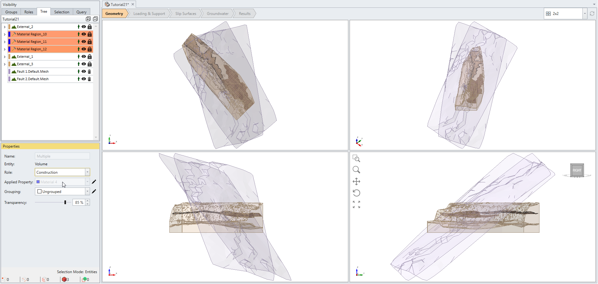
- You will notice that Material Region_12 has been identified as a small volume. We want to exclude this from collapsing. De-select Material Region_12 by hovering over it in the Visibility pane, hold ‘Ctrl’ key, and left mouse-click (Ctrl + left click).
- Finally select the Collapse button in the dialog with only the external layers selected.
- Click Close after the collapse is done.
3.0 Concept of Sequential Divide All and the Use of Construction Role
Any model can be further divided with new geometries. In this example, we continue to build the model with additions of two fault surfaces.
- Select Geometry > Import/Export > Import Geometry

- Select the Tutorials > Guide To New Divide All - starting file folder and open both files of "Fault 1" and "Fault 2" with ".rsgeomobj" extension.
- Select both geometries as shown below.
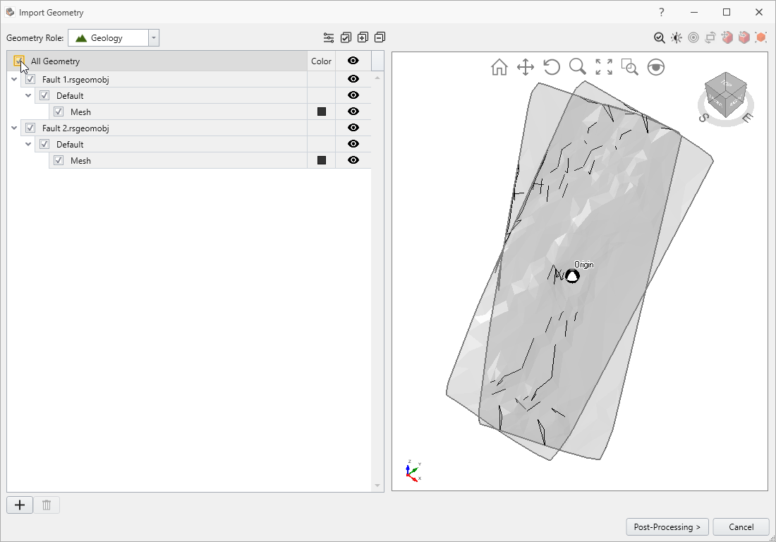
- Click Post-Processing and then select Done on the next screen.
Now you should see the following model:
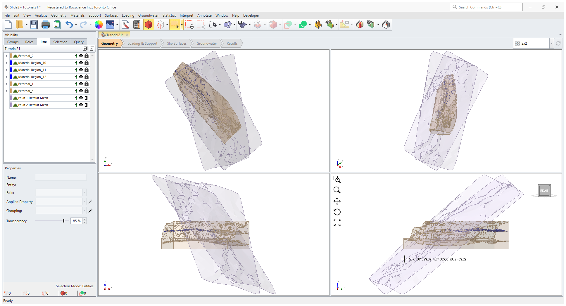
The imported fault surfaces cut through the entire external volume, as can be seen. You can rotate the view to inspect where the geometry meet between the external pieces and the fault surfaces.
Before selecting Divide All Geometry again, we wish to keep Material Region geometries in tact without being further split by the fault surfaces. In order to exclude geometry pieces from participating in Divide All process set them as Construction. To do so:
- Select Material Region_10, Material Region_11, Material Region_12 under the Visibility pane.
- Set Role to Construction in the Properties pane.
- Now select Geometry > 3D Boolean > Divide All Geometry. Don't change the Default setting in the Divide All Parameters dialog and select OK.Note: Try to run the second Divide All step without changing the role of the Material Region geometries and observe the difference.
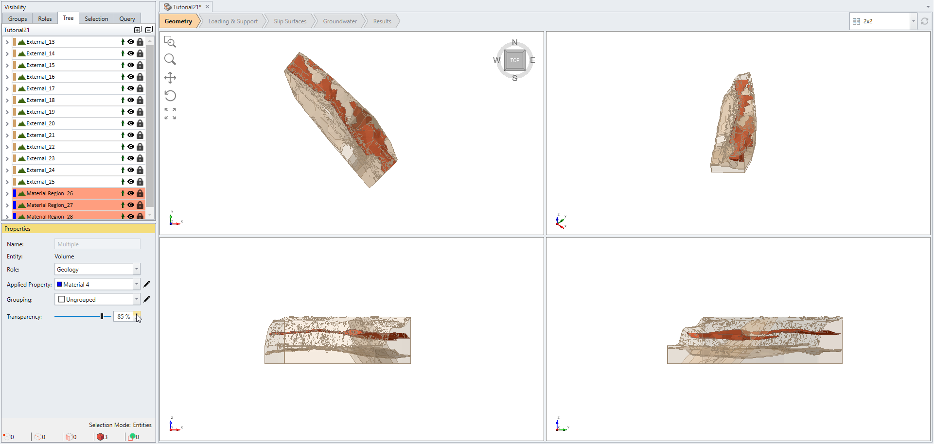
- Change back the Role of the Material Region from Construction to Geology for all three Material Region geometries.
Switch to a different perspective or rotate the view to observe the integrity of the three Material Region geometries and the other external pieces have been effectively split by the fault surfaces.
4.0 Union External Pieces to Remove Unwanted Regions
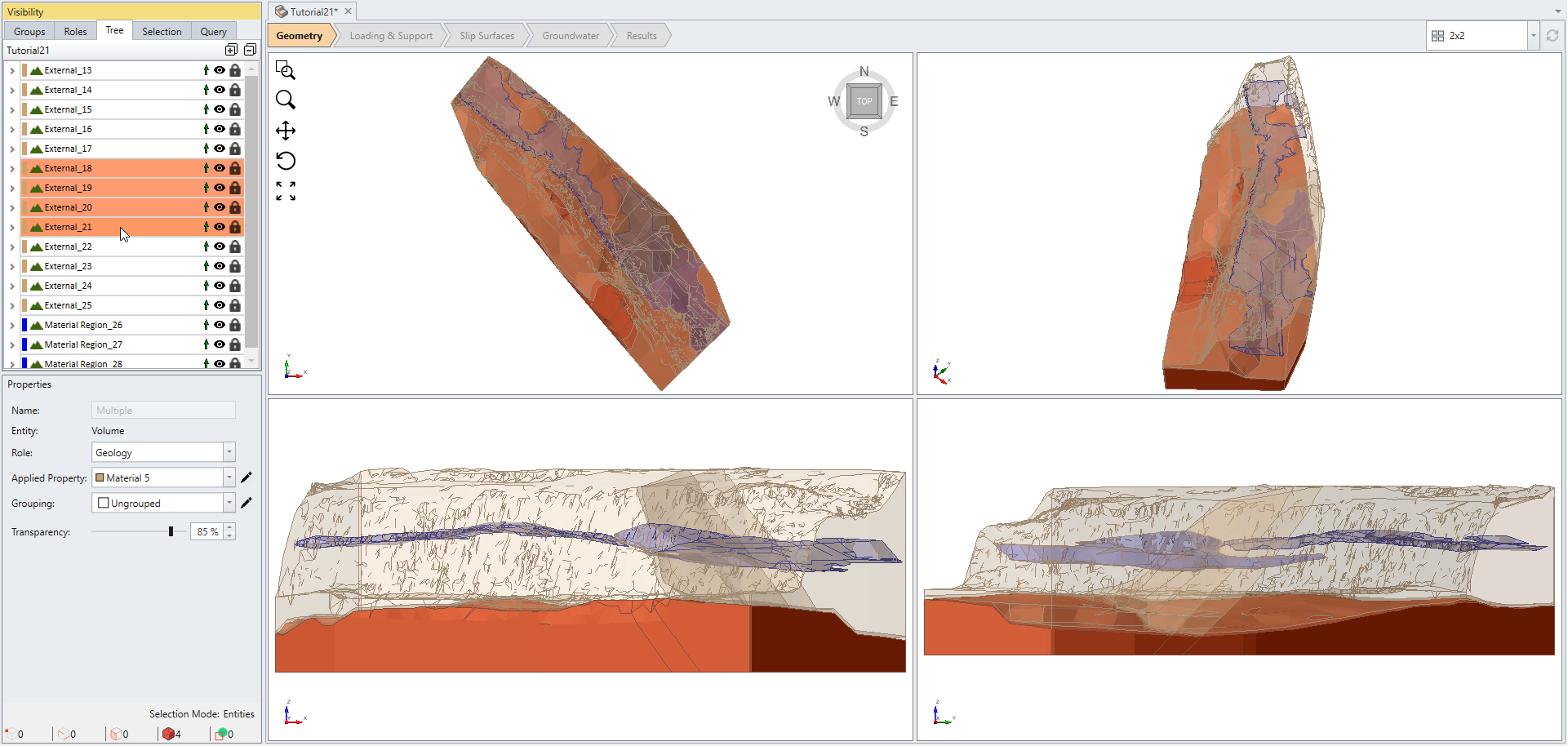
The final step of this tutorial demonstrates that Union function can also be useful to remove unwanted region splits. In this example, we wish to merge back the bottom external pieces as one geometry.
- Select entities as shown on the image below:
- Select: Geometry > 3D Boolean > Union
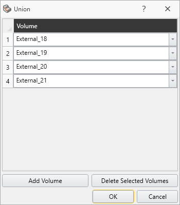
- Click OK in the Union dialog.
The Union function glues the four selected external pieces back in one. Notice that this function is also useful for removing unwanted volumes similarly to Collapse Small Volumes. 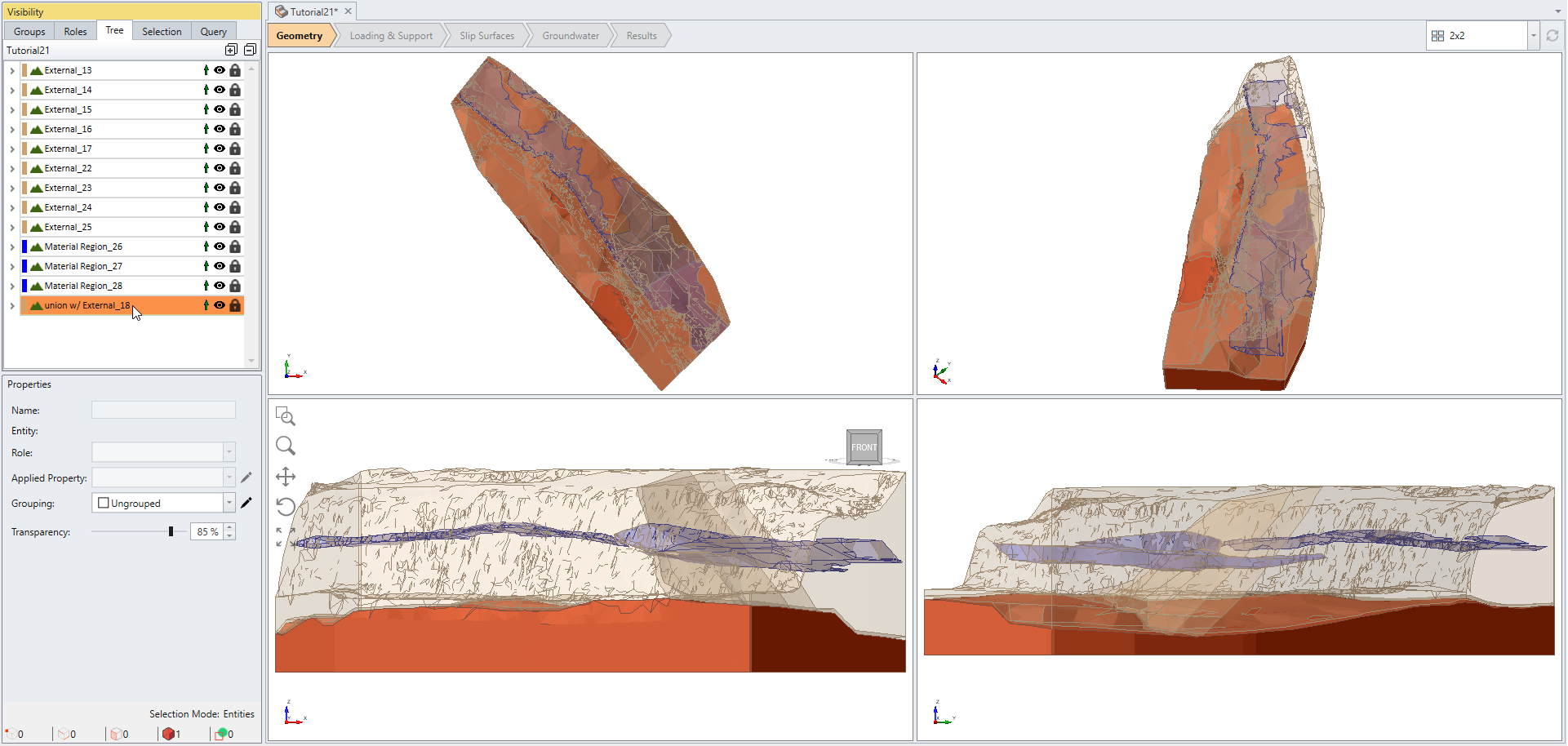
The difference between the two is the Union function requires a conscious choice of which volumes to merge, whereas Collapse Small Volumes automatically picks an adjacent geometry that shares the larger contact area for merging.