Stability of Dam
1. Introduction
This model demonstrates how to create a 3D model of a dam across a valley.
- Select File > Recent > Tutorials and open the file Stability of Dam – starting file.slmd.
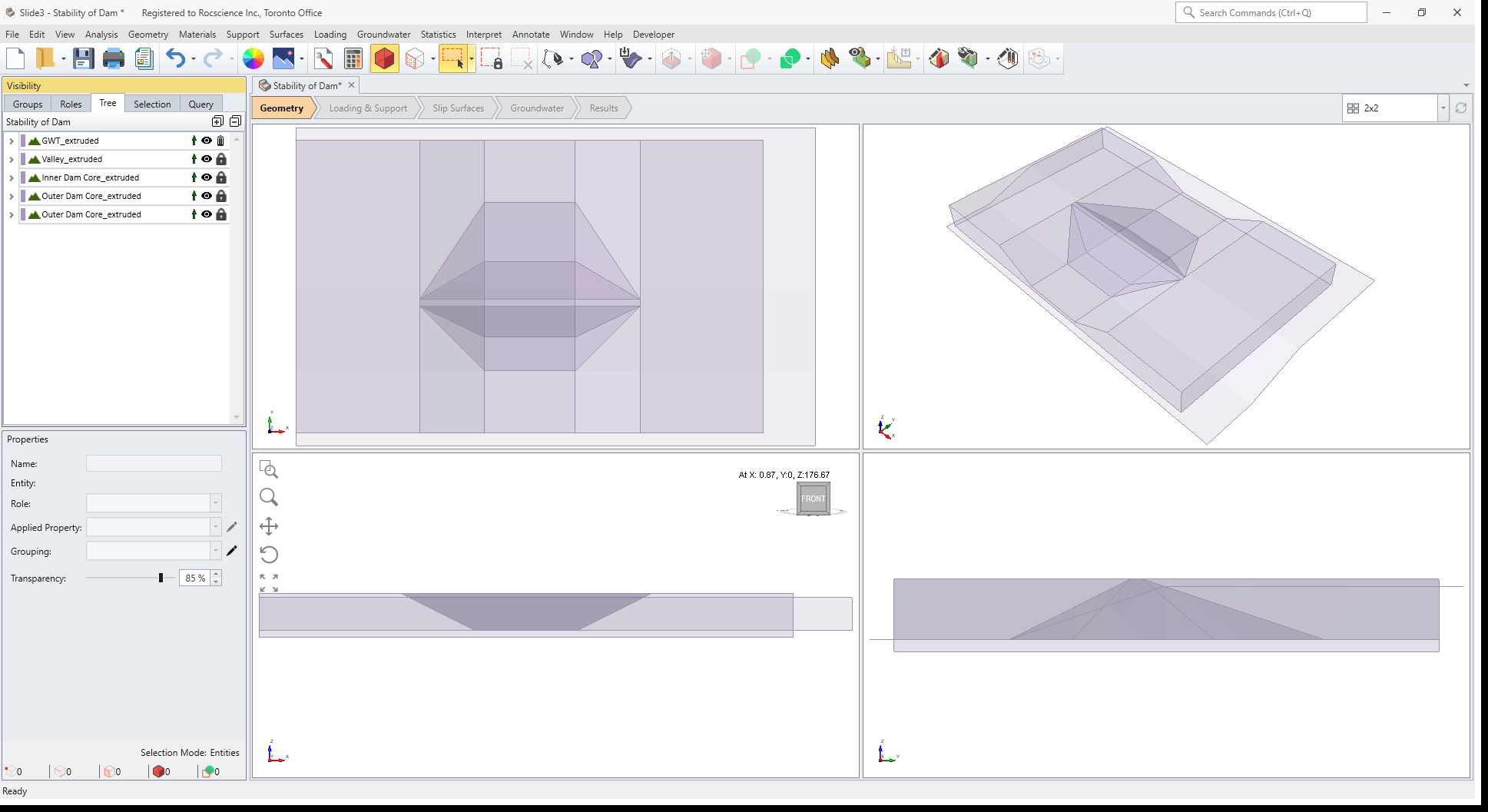
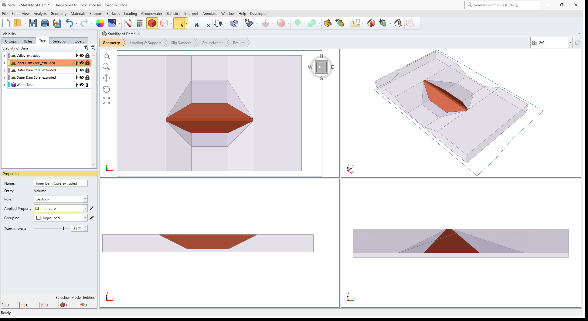
This file contains the cross-sectional profile geometry of a valley, dam and water table, as shown below.
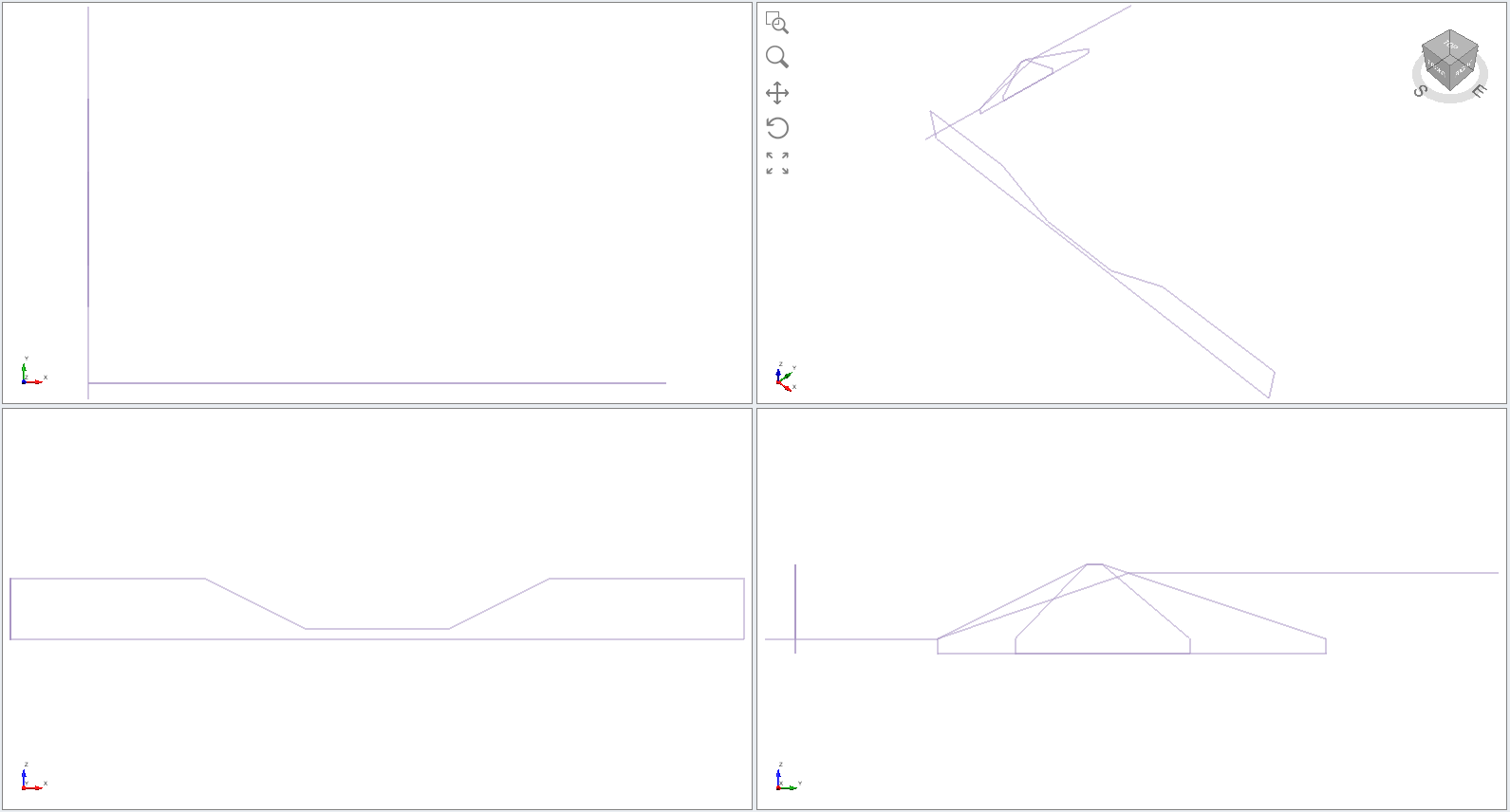
The coordinates were entered using the Draw Polyline option, and pasting x,y,z coordinate values into a table, as described in Tutorial 01 - Simple Extruded Slope with Water Table.
2. Project Settings
- Select Analysis > Project Settings
 to open the Project Settings dialog.
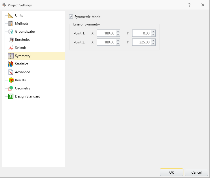
 - In the Symmetry tab, tick the Symmetric Model checkbox.
- To set the line of symmetry running through center of the model, enter the points (x, y) = (180, 0) for Point 1 and (x, y) = (180, 225) for Point 2.
- Click OK.
3. Extrude
3.1 EXTRUDE VALLEY
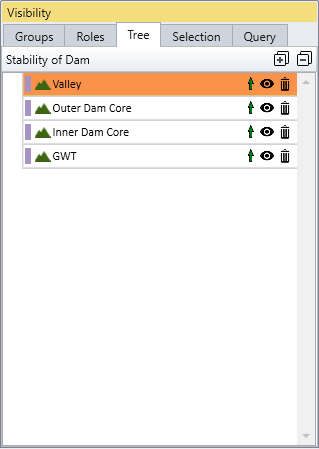
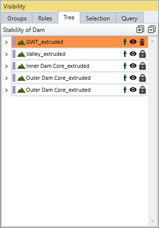
- Select the Valley entity in the Visibility Tree.
- Select: Geometry > Extrude/Sweep/Loft Tools > Extrude

- In the Extrude dialog, enter Depth = 225 and tick the Close Volumes checkbox.
- Click Preview to preview the result before finalizing.
- Click OK to extrude the valley 225 m in the y-axis.

3.2 EXTRUDE DAM
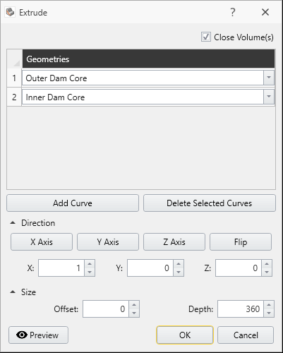
- In the Visibility Tree, select the Outer Dam Core and the Inner Dam Core entities.
- Select: Geometry > Extrude/Sweep/Loft Tools > Extrude

- In the Extrude dialog, enter Depth = 360 and tick the Close Volumes checkbox.
- Click Preview.
- Click OK to extrude the dam geometry 360 m in the x-axis.
3.3 EXTRUDE WATER TABLE
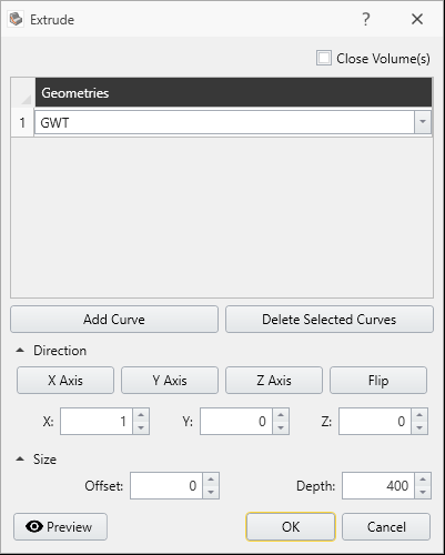
- In the Visibility Tree, select the GWT (ground water table) entity.
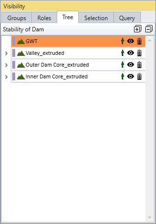
- Select: Geometry > Extrude/Sweep/Loft Tools > Extrude
- In the Extrude dialog, enter Offset = 0, Depth = 400.
- Click Preview.
- Click OK to extrude the water table 400 m in the x-axis.
4. Add to External
4.1 Set Valley Volume as External
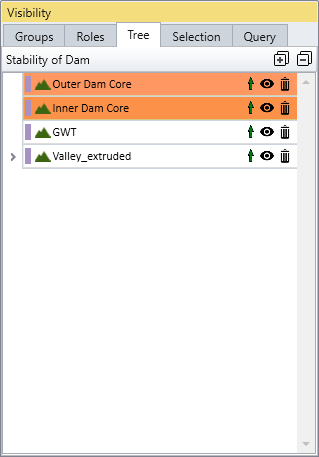
- In the Visibility Tree, select the Valley_extruded entity.
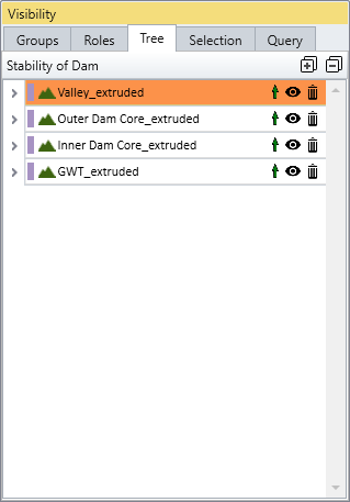
- Select: Geometry > Set as External
4.2 Add Inner Dam/Outer Dam volume to External
- Select the Inner Dam Core in the Visibility Tree.
- Select: Geometry > Add to External
- Select the Outer Dam Core in the Visibility Tree.
- Select: Geometry > Add to External
This automatically intersects the dam geometry with the valley geometry and creates a union forming the External boundary.
The order of adding entities to external matters. If you add Outer Dam core first and then add Inner Dam core you will get a dividing error and the add to external process won’t be accomplished properly
5. Set Water Table as Surface
- Select the GWT entity in the Visibility Tree.
- Select the Groundwater workflow tab.
- Select: Groundwater > Add Water Surface
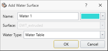
- Click OK in the Add Water Surface dialog.
The GWT (ground water table) has now been assigned as a water surface.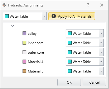
- Click OK in the Hydraulic Assignments dialog to assign the Water Table as the water surface for all materials.
6. Material Properties
- Select: Materials > Define Materials
 . The three materials have already been predefined (valley, inner core, outer core).
 - Select the Water Parameters tab in the Define Materials dialog to verify that the water table has been assigned to each material.
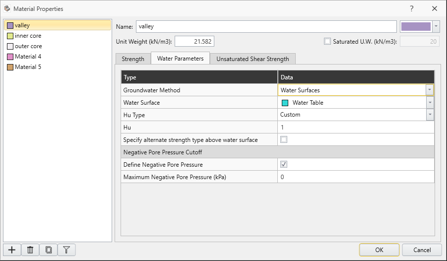
- Click OK or Cancel to close the dialog.
6.1 ASSIGN MATERIALS
- In the Visibility tree, select the Valley, Inner Dam Core and Outer Dam Core entities and assign the corresponding materials to each by selecting them from Applied properties in the Properties pane.
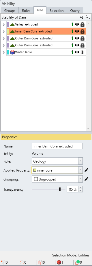
- Or select: Materials > Assign Materials. Then select the entity in the model by clicking on it and assigning it to its corresponding material.
The outer core has two sections, upstream and downstream; each must be assigned the outer core material.
7. Surfaces
- Select Surfaces > Slip Surface Options.
- We will use Spline surface search with Surface Altering Optimization.
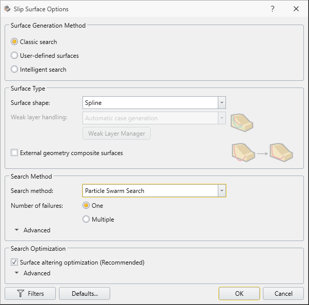
- Click OK.
8. Compute
- Save
 the file.
 - Select Compute
 in the toolbar (or select Analysis > Compute) to run the analysis.
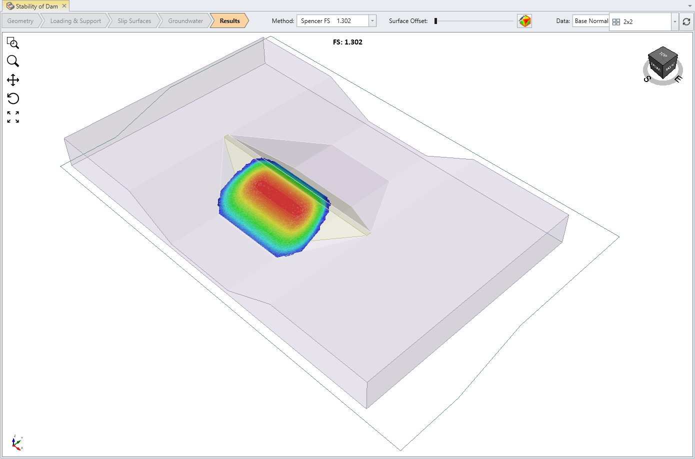
The Spencer results are shown below:
This concludes the Stability of Dam tutorial.