Mesh Quality
The Mesh Quality options allow you to detect and troubleshoot problems which may exist with the finite element mesh. If you are experiencing problems with your analysis (e.g. non-convergence of solution, aborted computation, warning or error messages during computing, unusual analysis results), then it is advisable to check for mesh problems with the Mesh Quality options.
Overview
In a finite element mesh, it is generally desirable to avoid elements of high aspect ratio (i.e. long "thin" elements). The presence of such elements can have adverse effects on the analysis results.
- In general, such elements can influence analysis results, and lead to misleading and inaccurate results, which are dependent on the mesh.
- In extreme cases, such elements may even be responsible for non-convergence of the finite element solution, and the analysis will be aborted.
In order to help the user determine the "quality" of a finite element mesh, EX3 can automatically locate and highlight elements in a mesh, which are deemed to be of "poor" quality, according to user-definable criteria. This is done with the Mesh Quality  option.
Mesh Quality
In order to locate and highlight poor quality elements in a mesh:
- Select the Mesh
 workflow tab.
 - Select the Mesh Quality option from the toolbar or the Mesh menu.
- The Mesh Quality Settings dialog should appear.
- Use the dialog to view any poor quality elements based on the defined criteria. If poor quality elements exist, they will be highlighted.
The elements which are highlighted, are those which conform to the criteria of a "poor quality" element, as defined by the Mesh Quality Metrics (see below). In most cases, you will need to zoom in to get a good view of the highlighted poor-quality elements and determine what may be the cause of the problem. Each metric has a set colour that will be used to show the elements that are within a particular metric query range.
After you generate the mesh for a model, it is always a good idea to use the Mesh Quality option to see if there are any problems with your mesh.
Mesh Quality Metrics
You can define the mesh quality criteria in the Mesh Quality Settings dialog. The shape quality metric query value can range from 0 to 1. This is based on the quality of tetrahedron which can be calculated using the formula below:
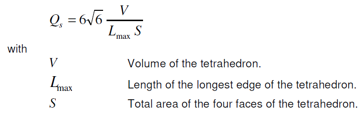
This implies that the closer Qs is to 1, the more four triangles of the tetrahedron are equilateral.
If you choose the quality min/max value from 0 to 1, it will select every element in the mesh. On the other hand, if you change the range from min = 0.5 to max = 0.5, it will only select the element that has quality exactly at 0.5.
Reasons for poor quality mesh elements
There are various reasons why poor-quality mesh elements may be generated. Typically the problems are due to:
- Vertices which are very close to each other.
- Poorly graded mesh (for example, a finely discretized boundary immediately adjacent to, or close to, a coarsely discretized boundary, will often result in a poor quality mesh).
- The geometry of your model boundaries, for example, the relative distances between boundaries, or the way in which they intersect (e.g. nearly parallel boundaries which intersect at a very small angle).
Fixing a poor quality mesh
- If the problem is vertices which are very close to each other, then you may need to delete unnecessary vertices, or move vertices so that they are further apart, or exactly coincident. If vertices were intentionally located very near to each other, and this is causing a problem, then you may want to consider modifying your geometry slightly, so the poor-quality elements are not generated.
- If a poor grading is responsible for the poor mesh, then you may need to customize the mesh. This may involve the use of the Mesh Settings or Mesh Refinement options.
- If the actual model geometry is responsible (e.g. very thin material layers), then various solutions might be appropriate, involving Mesh Settings or Mesh Refinement options, or modifying the boundaries slightly, so that the problem does not occur.