Geometry Cleaning Overview
1.0 Introduction
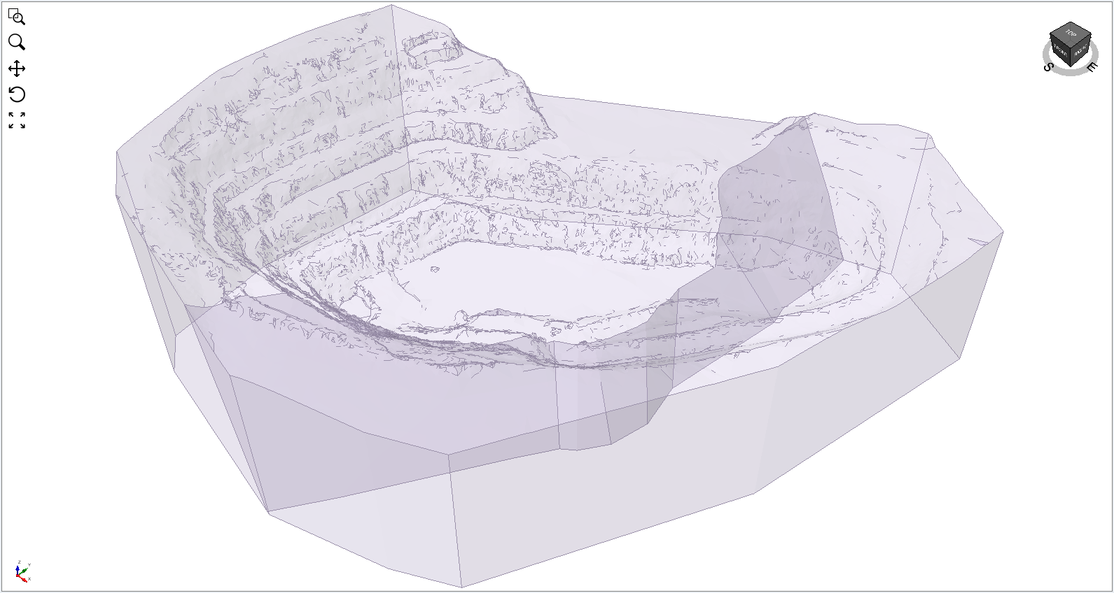
This tutorial will demonstrate how to use the automatic functionality in the Geometry Repair tool included with Slide3, in addition to some other useful Surface Triangulation Tools. Previous versions of Slide3 required that users repair defective geometry using third-party software prior to importing in to Slide3. Now, the inclusion of geometry cleaning tools allows the geometry to be repaired within Slide3 itself. This tutorial uses an open pit model with a pit surface and a vertical geological surface. We will use the Geometry Repair tool and some Surface Triangulation Tools on the individual entities to prepare them for the Divide All Geometry operation.
2.0 Open the Model
- Select File > Recent > Tutorials and read in the file Geometry Cleaning – Overview – starting file from the installation folder.
The project includes a pit surface, a polyline to define the extents in the X and Y directions, and a polyline that will be used to define a vertical geological surface.
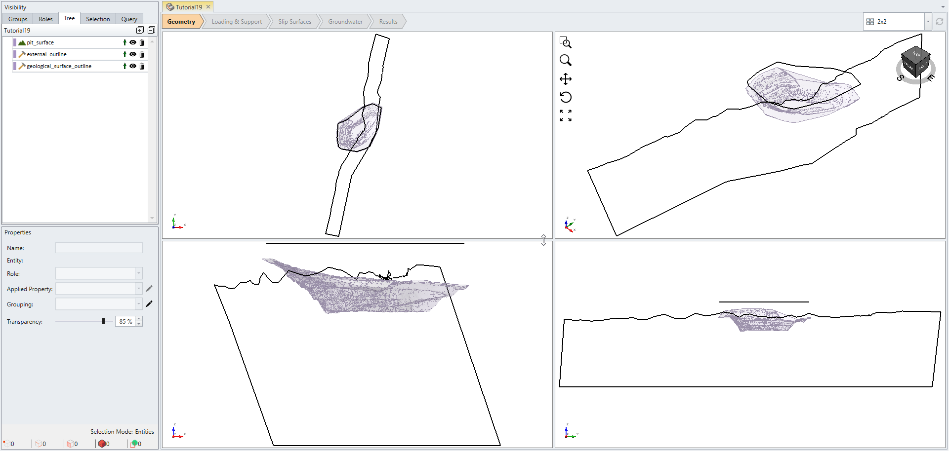
In the following we will use the Geometry Repair tool on the pit surface, and some Surface Triangulation Tools on the polyline and vertical geological surface.
3.0 Geometry Repair Tool
- Click on the pit surface in the Visibility pane on the left side of the program.
- Select Geometry > Repair Tools > Repair.
You should be able to see the Repair Geometry dialog.
The tool will search the geometry for defects. The more complicated the geometry, the longer this will take. The tool then presents four panels.
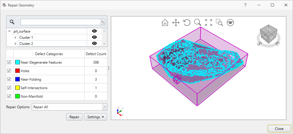
The main view shows a 3D view of the geometry, and its color-coded defects. The colors correspond to those in the Filtered Results panel. The magenta boxes group the defects into clusters. They can highlight defects that might otherwise be too small to see. For example: there is one Self-Intersection near the South edge of the pit that might be difficult to see.
The Filtered Results panel contains: a list of defect categories; the number of defects in each category; the color of the defects drawn in the 3D view; and the option to exclude a defect category from the Repair operation.
The list of individual items groups the defects by entity, then cluster. Click the Eye ![]() icon to hide or show a given entity, cluster, or defect, in the 3D view. You can search for entities, clusters, or defects using the Search bar above this list. For example, type “intersect”, then click the Find button (or type ) to search for items containing that text. Click the X in the Search bar (or type ) to clear the search.
icon to hide or show a given entity, cluster, or defect, in the 3D view. You can search for entities, clusters, or defects using the Search bar above this list. For example, type “intersect”, then click the Find button (or type ) to search for items containing that text. Click the X in the Search bar (or type ) to clear the search.
The repair panel contains Repair Options, the Repair button, and an optional Settings area.
The default Repair Option is Repair All. This is the most automatic way to repair geometry. For more information on Repair settings option, please refer to Geometry Repair Tool which describes the repair selection options.
Repair All option first invokes the Re-Triangulate tool (Geometry > Surface Triangulation Tools > Re-Triangulate) on the entirety of each entity; this is a global operation that often fixes many defects just by itself. Then it iteratively fixes the remaining defects, up to a maximum number of iterations.
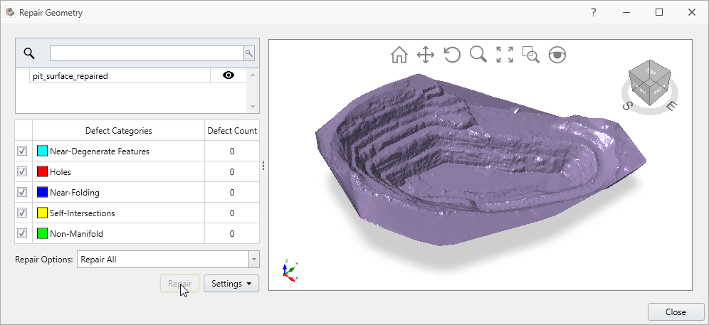
- Click the Repair button now to automatically fix the geometry. The more complicated the geometry, and the more defects there are, the longer this will take. Once complete, the tool presents you with an updated look at the geometry. The tool was able to automatically fix all defects on this particular pit surface.
The Repair tool has added the repaired geometry to the model; the Name of the entity has been appended with “_repaired” as shown below.
- Click the Close button to dismiss the tool.
4.0 The External Volume
The pit surface’s boundary is still overly detailed in some areas, so we will define a volume that excludes the boundary. This is another way to deal with bad geometry: leave it outside of your External volume.
- Click the external_outline polyline under the Visibility pane.
- Select: Geometry > Extrude / Sweep / Loft Tools > Extrude or select Extrude
 from toolbar.
 - We will extrude the geometry by a Depth of -200, and ensure Close Volume(s) is enabled.
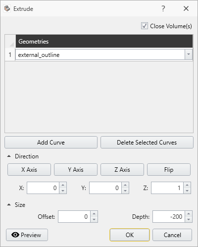
- Click OK to create the volume.
- Ensure the Role of the new volume is set to Geology. To do so, select extrnal_outline_extruded under the Visibility pane, change its Role from Construction to Geology under the Properties pane bottom left.
- We will now use the pit surface to cut away the top of the extruded volume. Click the pit_surface_repaired and hold Ctrl and select external_outline_extruded under the Visibility pane to select them both.
- Select Geometry > 3D Boolean > Split.
- The tool should have automatically identified the external_outline_extruded volume as the Volume to Split, and the pit_surface_repaired as the Splitter.
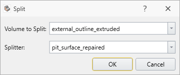
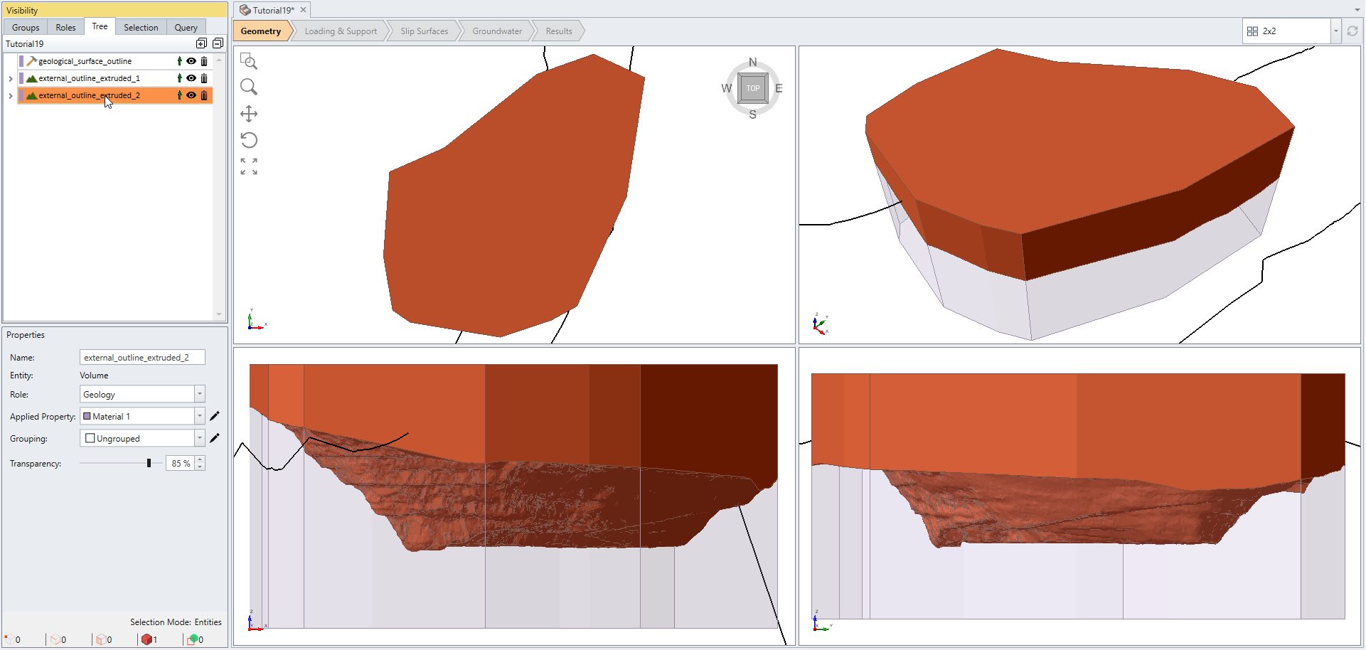
- Click OK to perform the Boolean operation.
- You will see the following volume has been split into two layers. Select the top layer of the open pit model and change the role to Construction in the visibility tree.
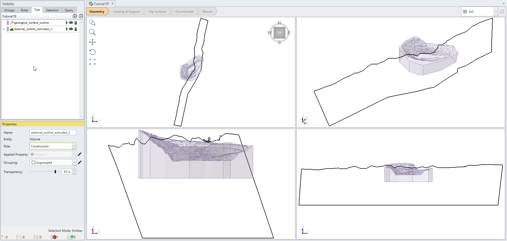
- While the top layer is still selected, select Geometry > Delete Selected Construction Geometry
 .
.
Then, you will see the following geometry as shown below.
The volume that defines the model’s extents has now been prepared, so we will set it as the External. To do so:
- Click on the subtracted volume to select it.
- Select Geometry > Set as External.
5.0 Surface Triangulation Tools
Slide3 includes several other tools to help improve or otherwise manipulate geometry. We will use Create Triangulation From Closed Polyline, Merge, and Re-Triangulate, to create a vertical geological surface from a closed polyline. First, we will fill the interior of a closed polyline to create a surface.
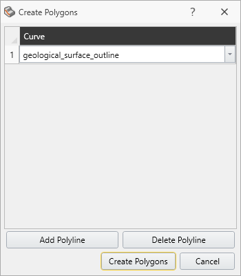
- Click on the geological_surface_outline polyline entity.
- Select Geometry > Surface Triangulation Tools > Create Triangulation From Closed Polyline

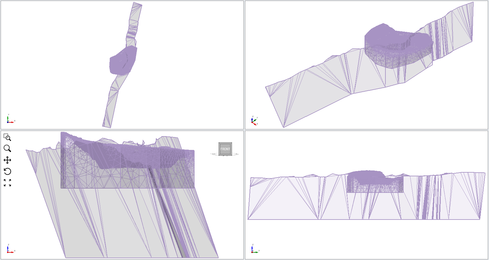
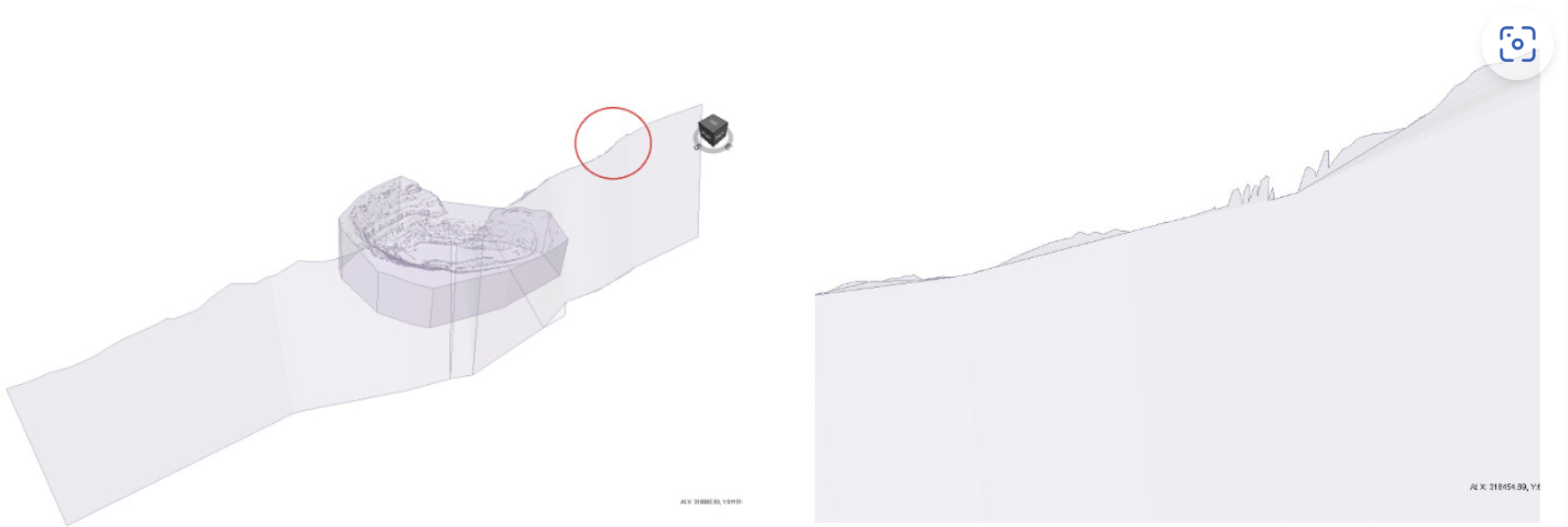
- Click on Create Polygons to fill the polyline. This creates the simplest triangulation inside the polyline, without modifying the actual polyline, or adding any vertices in the surface interior. Zooming in to the top of the surface shows several unnecessary protrusions.
- Select View > Show All Edges. Show All Edges allows you to see the triangulation on all surfaces. In this case, there are several large and narrow triangles.
- We will use more Surface Triangulation Tools to generate a better surface. Turn off the edge rendering by selecting the menu item (Show All Edges) again.
- Click on the Polygon 1 under the Visibility pane.
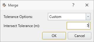
- Select Geometry > Surface Triangulation Tools > Merge. We will use the Merge tool to collapse clumps of vertices within a given tolerance. Change the Tolerance Options to Custom. Enter an Intersect Tolerance of 5.
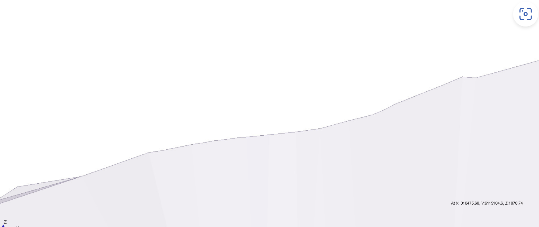
- Click OK to merge the geometry. This produces a much neater boundary.
- Click on Merged entity to select it.
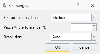
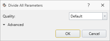
- Select Geometry > Surface Triangulation Tools > Re-Triangulate. We can use the default settings for now.
- Click the OK button.
- Use View > Show All Edges again to see the effect of Re-Triangulate on the surface interior.
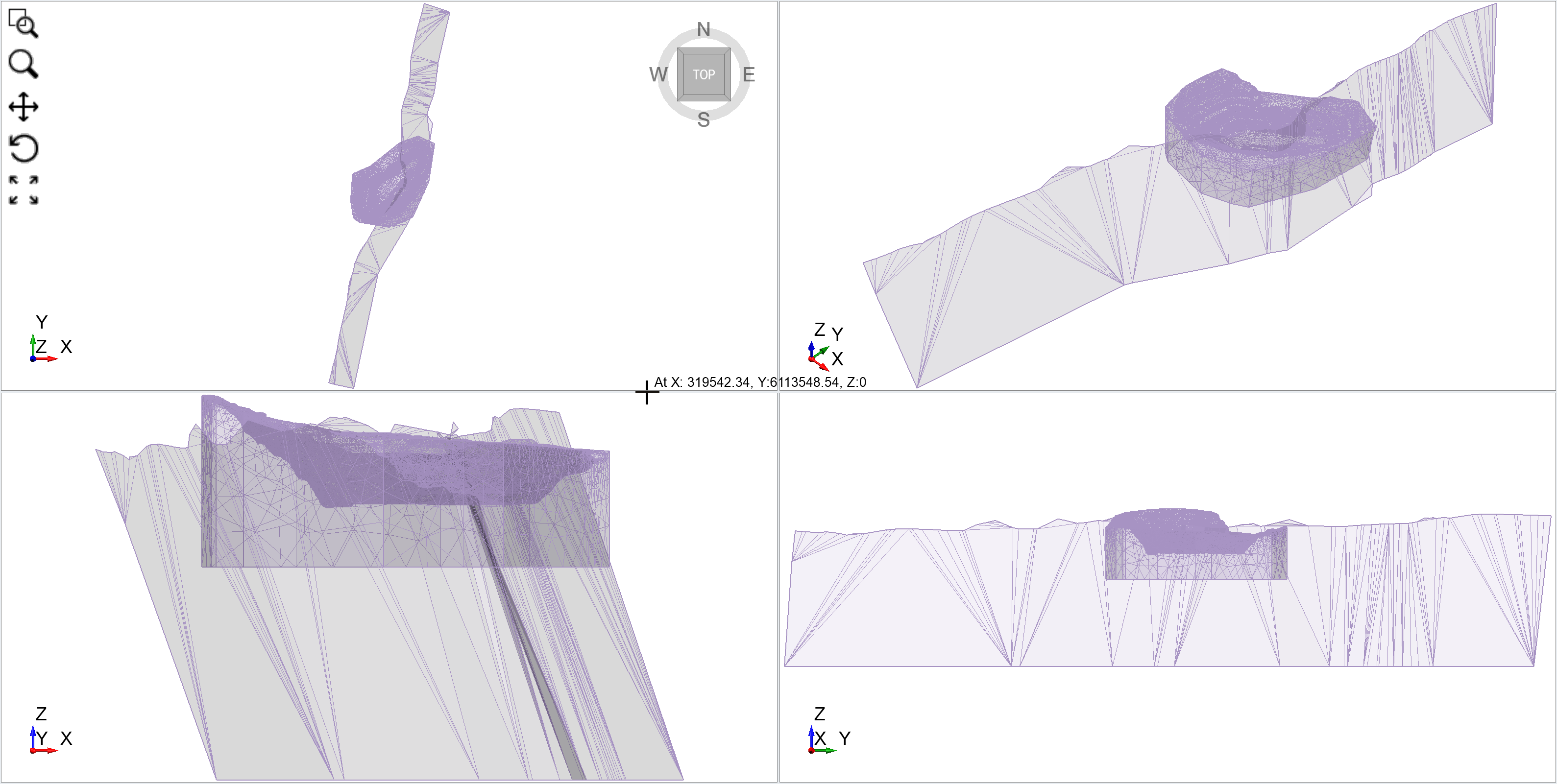
- Turn if off when you are done.
Since no vertices were added to the interior of the surface, the Merge tool only improved the quality of the boundary. We will use the Re-Triangulate tool to improve the quality of the interior.
6.0 Divide All Geometry
Now that the individual entities have been prepared, we can combine them in the Divide All Geometry operation.
- Select Geometry > 3D Boolean > Divide All Geometry

- Use the default settings, and click the OK button.
You can now assign geological materials, and continue with the non-geometric steps of the modelling process.