SSR Search Area
1.0 Introduction
In this tutorial, RS2 is used to determine the factor of safety of an embankment using the shear strength reduction (SSR) method. The slope stability analysis is restricted to one side of the embankment by defining an SSR search area.

2.0 Import Slide2 Model
To import the model file into RS2:
- Select: File > Import > Import Slide
- Open the file SSR Search Area.slim found in the Examples > Tutorials folder in the RS2 installation directory.
Once the Slide2 file is open, the following dialog will appear:
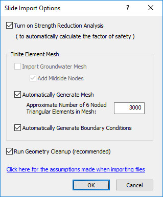
Let’s perform a shear strength reduction (SSR) analysis to determine the factor of safety for slope stability so leave this option on.
- Check the boxes for “automatically generate mesh” and “automatically generate boundary conditions” (Slide2 analyses do not require a finite element mesh so the mesh must be generated by RS2).
- Click OK to accept the defaults.
The model should appear as below:
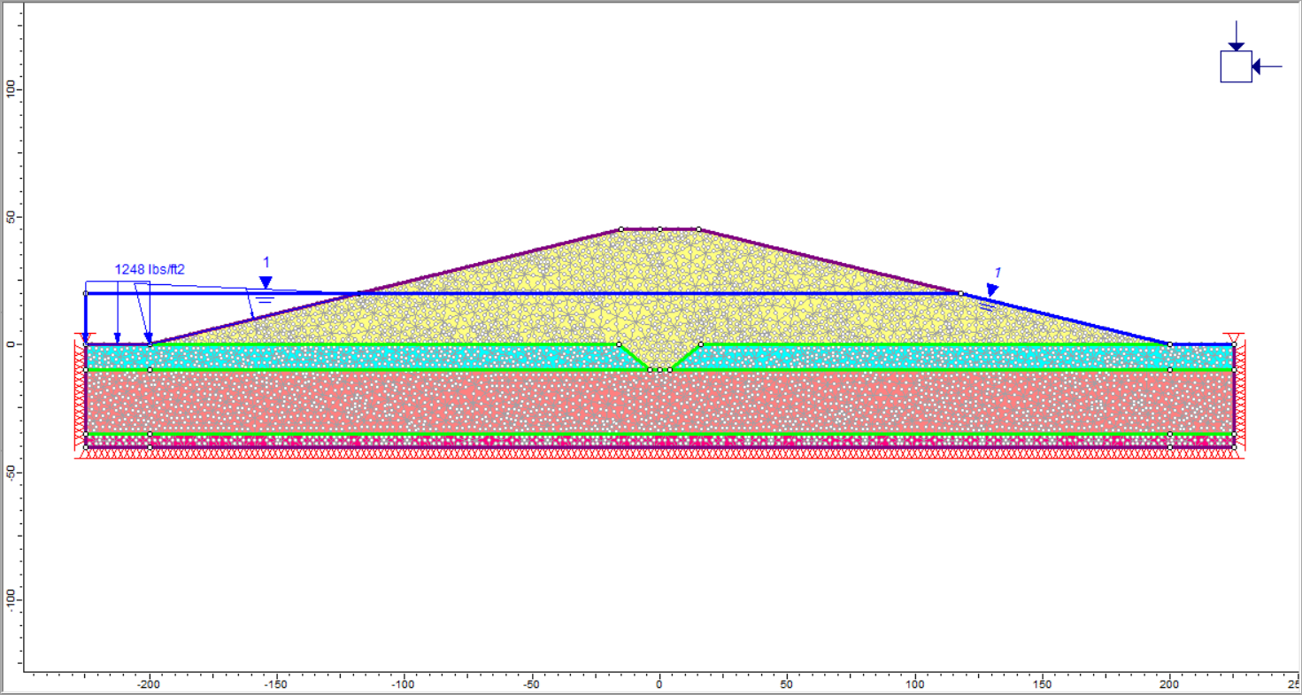
This model represents a sloped embankment built upon a sand layer overlying a foundation clay layer that sits on top of bedrock. The water table is 25 feet below the top of the embankment and ponded water exists at the left side of the model. The ponded water exerts a force on the soil as shown by the blue arrows.
3.0 SSR Analysis: Default Region
The model is already completely built. Save the file in RS2 format, then compute and analyze the file:
- Select: File > Save As

- Select: Analysis > Compute

- Select: Analysis > Interpret

The following plot shows the maximum shear strain in the model for the critical shear strength reduction factor. Clicking the tabs for higher SRF factors shows the development of a clear failure surface on the right side of the embankment.

 Displaying the deformation vectors clearly shows the displacement of the slope on the right side with very little
deformation on the left side.
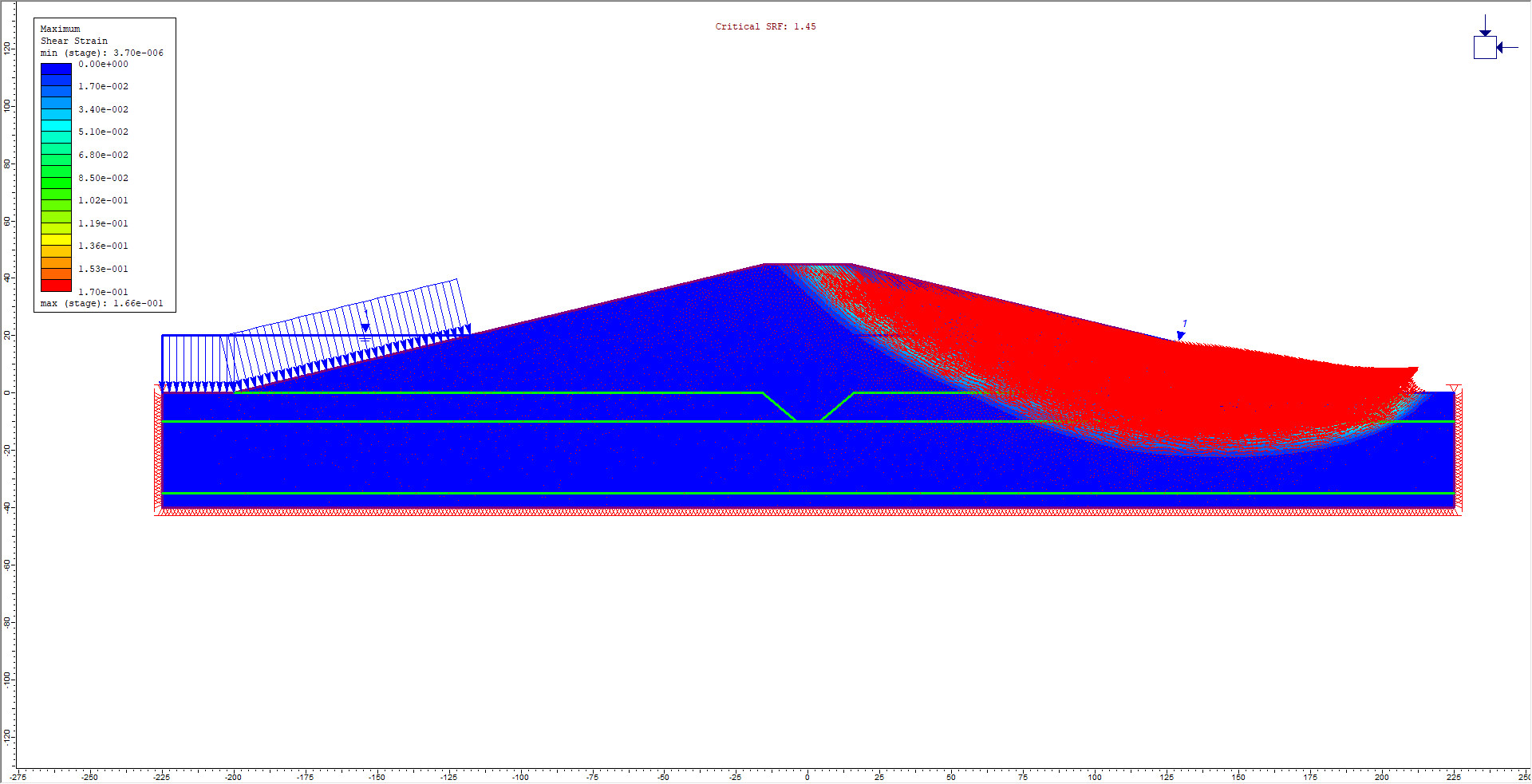
In an SSR analysis, RS2 automatically finds the slope failure mechanisms associated with the minimum shear strength reduction (minimum factor of safety). In this case, the most likely failure occurs on the right side of the embankment. To further analyze a specific area in the model, the SSR Search Area in RS2 can be defined.
4.0 SSR Search Area Defined
- Go back to the RS2 model program.
- Select: Analysis > SSR Search Area > Define SSR Search Area (window)
- The mouse will now appear as crosshairs. Enter two points to define two diagonally opposite corners of a rectangular area. To encompass the left side of the model, enter: (-250, 100) and (40, -60).
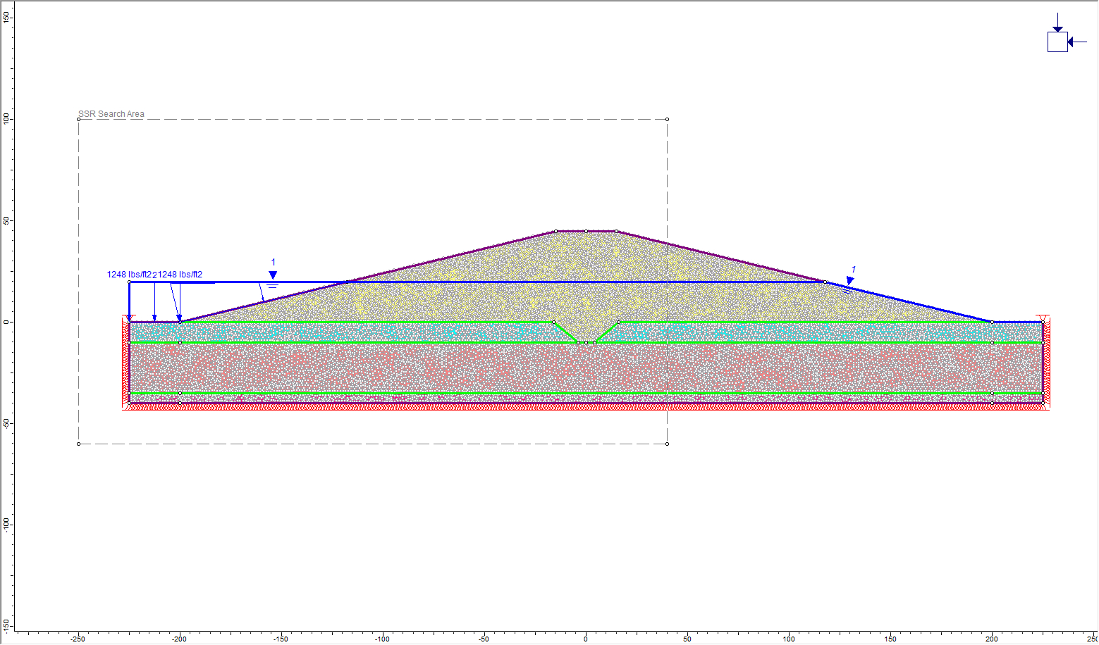
- The search area can be easily resized or moved by right-clicking on one of the corner points and selecting Move To.
- The search area can be deleted by selecting Analysis > SSR Search Area > Delete SSR Search Area
- Save the file under a different name (as the search area has been modified).
- Proceed with computation and analysis by selecting Analysis > Compute

5.0 Results and Discussion
- Select: Analysis > Interpret

A screen is now displayed with the critical strength reduction factor (SRF) at the top of the window. Click through the higher SRF plots to see the development of a failure zone on the left side. The plot below shows the maximum shear strain for SRF = 2.12.
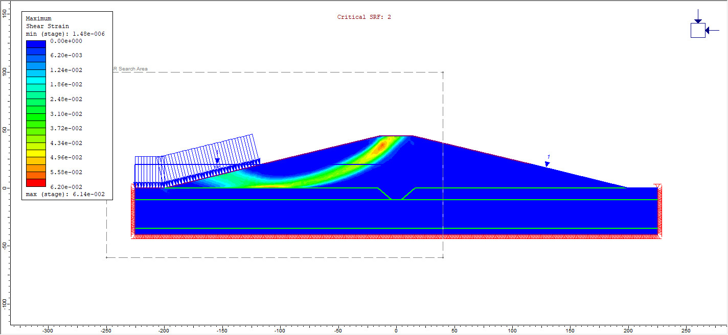
Note that the critical SRF for this analysis (2.0) is higher than the critical SRF of the previous analysis with no search area defined (SRF = 1.48). This indicates that the left side of the embankment is more stable than the right. RS2 did not show failure on the left in the previous analysis since it shows the failure mode with the lowest factor of safety (unless the search area is restricted). There is a difference in stability between the left and right sides due to the stabilizing effect of the ponded water force on the left side of the embankment.
A direct comparison of the Slide2 analysis with the RS2 analysis can be performed. Open the Slide2 model in Slide2 Interpret; a circular failure surface should be visible, as shown below:
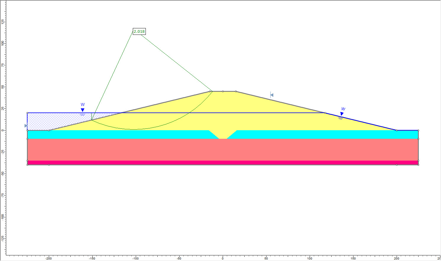
In the Slide2 Interpreter:
- Right-click on the failure surface and select Copy (Slide2 modeller format).
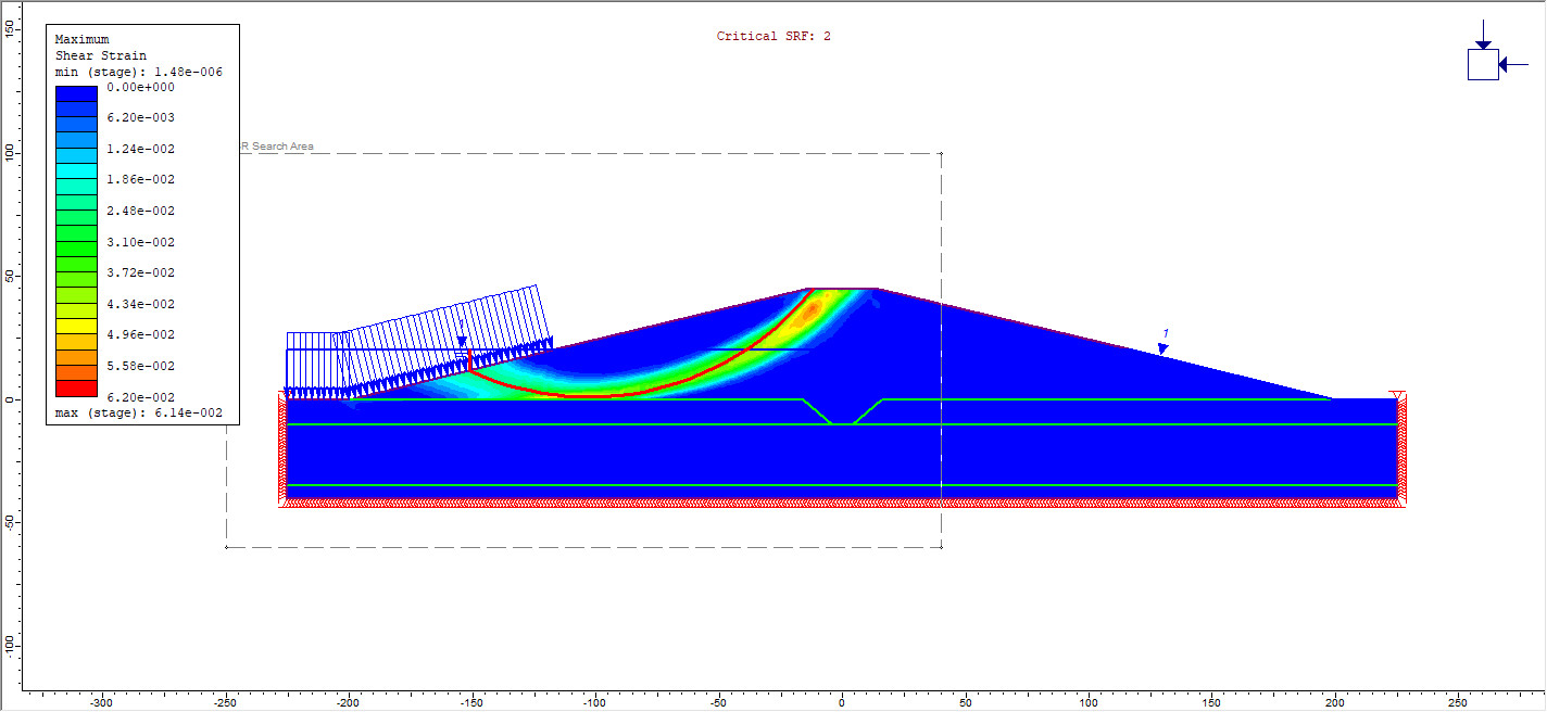
- Go back to the RS2 Interpret window and choose the plot for SSR: 2.12.
- Go to the Edit menu and choose Paste from Slide2 Interpret.
- The failure surface will now appear on the plot as a black line. Change the appearance of the line by right-clicking and selecting Format. Change the colour to red and the weight to 4. Click OK.
This concludes the SSR Search Area Tutorial.