Piled Raft Foundation
1. Introduction
In this tutorial, RS2 is used to simulate a piled raft foundation. The raft is modelled using a composite liner which considers the soil-raft interaction using a joint layer. The piles are modelled using pile supports which have beam and interface components. The beam captures the structural behaviour while interface captures the soil-pile interaction behaviour. The model was constructed in two stages:
- Soil is brought to equilibrium.
- Piled raft foundation is installed and load is applied.
2. Constructing the Model
- Select: File > Recent Folders > Tutorial Folder > Supports
- Select the Piled Raft Foundation (initial) starting file.
In the starting model file, project settings have been defined, the external boundary has been created, a piezometric line has been added, field stress is set, and material properties are defined. The tutorial will proceed to create a raft, create piles, and add a load to the raft.
2.1 PILES
Pile supports are to be added before meshing while composite liners must be added after meshing. The piles will be installed in Stage 2, so click on the tab to show Stage 2.
- Select: Support > Add Pile
- Leave the assigned Pile Property as Pile 1.
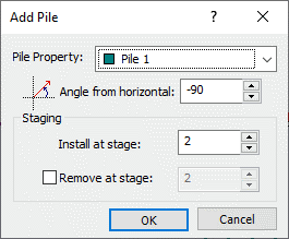
- Under Staging, make sure Install at stage is set to 2.
- Press OK to select the pile head locations. The pile length will be defined in the pile properties described later.
- Enter the following pile head locations and press Enter in between points:
- First pile: (74, 0)
- Second pile: (78, 0)
- Third pile: (82, 0)
- Fourth pile: (86, 0)
As mentioned previously, the pile support has beam and interface components. The interface captures the soil-pile interaction behaviour. Let’s start with the beam component which is defined using liner properties.
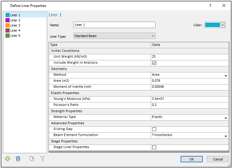
- Set the Young’s Modulus to 35,000,000 kPa
- Set the Poisson’s Ratio to 0.2
- Set the Area to 0.076 m2
- Set the Moment of Inertia as 0.00048 m4
- Turn on the Include Unit Weight in Analysis option and set the Unit Weight to 25 kN/m3
- Leave all other properties as the default values shown
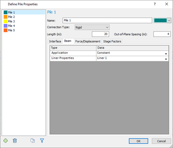
In the Pile Properties dialog, we will define the interface properties and assign the liner properties to the pile.
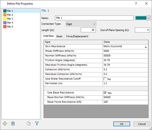
- Change the Connection Type to Rigid
- Set the Length to 20 m
- Change the Out of Plane Spacing to 4 m
- Set the Shear Stiffness to 5,000 kN/m/m
- Set the Normal Stiffness to 50,000 kN/m/m
- Assign the Friction Angle to 24.79 degrees
- Assign the Residual Friction Angle to 24.79 degrees
- Set the Cohesion to 3.2 kN/m/m
- Change the Residual Cohesion to 3.2 kN/m/m
- Change the Perimeter length to 1.1 m
- Set the Base Normal Stiffness to 50,000 kN/m
- Set the Base Force Resistance to 100 kN
- Leave all other properties as the default properties shown
In the Beam tab, the default options are sufficient as it should already reference Liner 1 properties that we defined earlier. There is an Application option to Define Beam segment by length which we do not explore in this tutorial. This option allows different liner properties to be used at distances along the pile to define the beam component.
The Force/Displacement and Stage Factors tabs are not needed for this tutorial.
2.2 LOADS
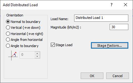
- Select Loading > Distributed Loads > Add Uniform Load
- Set the Magnitude to 30 kN/m2
- Click the check box for Stage Load. Click on the Stage Factors button.
- Set the Stage Factor for Stage 1 to 0 as no load will be applied during the first stage.
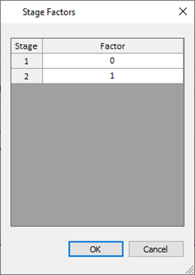
- Click OK to close the dialog.
- Click OK to close the Add Distributed Load dialog.
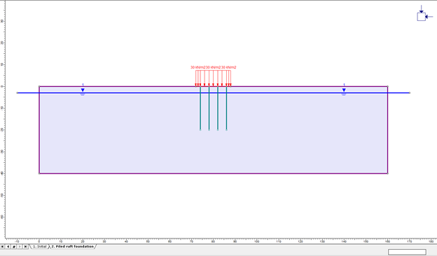
- Select the vertex to the left of the piles (72, 0). Trace the mouse to the right along the external boundary and select the vertex to the right of the piles (88, 0).
The final model for Stage 2 should now look like this:
2.3 MESHING
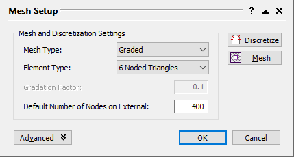
- Select Mesh > Mesh Setup

- Ensure the following properties are set:
- Mesh Type is set to Graded
- Element Type is 6-Noded Triangles
- Default number of Nodes on External is set to 400
2.4 RAFT
As mentioned previously, the raft is modelled using a composite liner which has liner and joint components. The joint layer captures the soil-raft interaction behaviour. Make sure you are still in Stage 2 of the model which is the stage in which the liner will be installed.
- Select Support > Add Liner

- Click the Composite Liner check box. Make sure the Install at Stage option is set to 2.
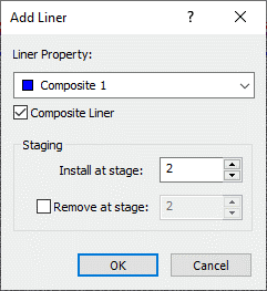
- Press OK to close the dialog and proceed with selecting the liner location.
- Select the five line segments underneath the uniformly distributed load along the Clay external boundary.
The image below has hidden the distributed load to make it easier to see the five line segments.
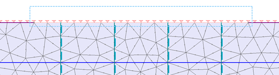
- Press Enter to apply the liner to the selected segments.
Next, the composite liner properties will be defined.
- Select Properties > Define Composite
- Set the Number of Layers to 1.
- Change the Liner type to Liner 2
- Click the Joint Interface check box.
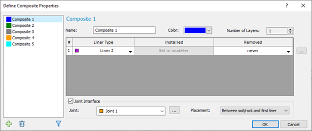
- Change the name to Raft Foundation.
- Set the Youngs Modulus to 35,000,000 kPa
- Change the Poisson’s Ratio to 0.2
- Set the Thickness as 0.5 m
- Click the Include Weight in Analysis check box and set the Unit Weight to 25 kN/m3.
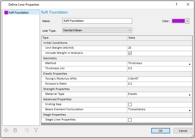
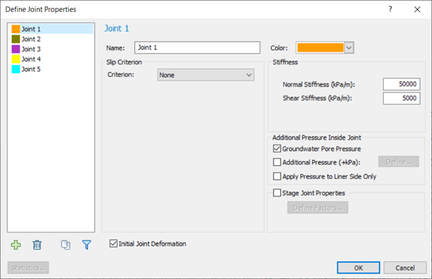
- Set the Normal Stiffness to 50,000 kPa/m.
- Set the Shear Stiffness to 5,000 kPa/m.
2.5 RESTRAINTS
The restraints needed for this problem are available as an Auto Restrain option.
- Select Displacements > Auto Restrain Surface (Pins).
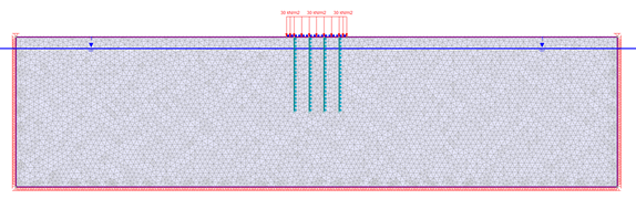
Stage 2 of the model should look as shown above after the restraints have been applied.
3 Compute
- Select Analysis > Compute

4 Results and Discussion
- Select Analysis > Interpret

- The maximum stress for Stage 1 will be displayed. Stage 1 only shows the stress due to gravity in the undisturbed material.
- Click the tab for Stage 2 to observe the stress after the installation of the piled raft foundation and applied load. There is not much change from Stage 1.
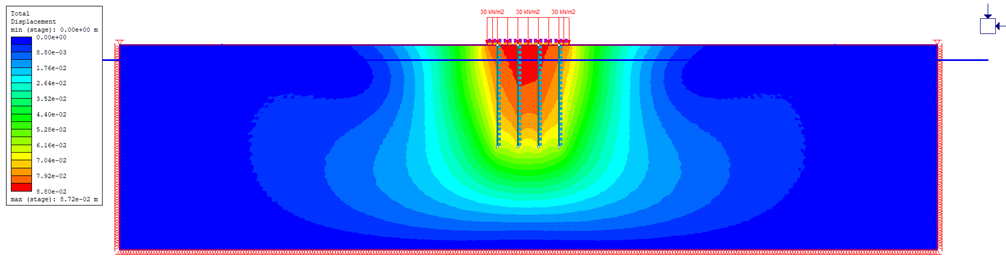
- Change the contours to plot Total Displacement using the drop-down menu in the toolbar.
The highest displacement, as expected, is in the center of the loaded piled raft foundation.
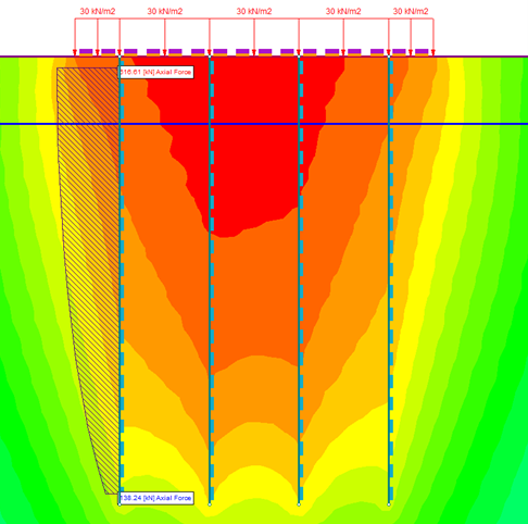
To view the axial forces along the piles, right-click on a pile and Select: Show Liner Values > Axial Force. The axial force distributions along the piles are now visible.
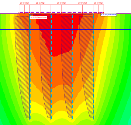
The results for only an individual pile can also be shown. To do so, right-click on the desired pile and select Show Liner Values > Show Values (just this liner on)