Profiles and Boreholes
1.0 Introduction
This tutorial illustrates how to introduce profiles and boreholes into a model with a simple surface excavation, consisting of a trench located near a circular tunnel and a distributed load directly above the tunnel. The gravity field stress option is used, and a staged analysis is performed by first excavating the tunnel, then the trench, and finally, adding the load in the fourth stage. Two boreholes are present, one located on either side of the excavations. The borehole profiles have three layers, with three different sandy materials. Results will then be analyzed using RS2 Interpret. For additional information, see Profiles and Boreholes in RS2.
2.0 Constructing the Model
- Select File > Recent Folders > Tutorials Folder.
- Open the starting file Profiles and Boreholes (Initial).
In this file, material properties have already been defined such that you can proceed with defining the boreholes.
2.1 Project Settings
- Select: Analysis > Project Settings

- In the Project Settings dialog, under the General tab, the units are set to Metric, stress as kPa.
- Select the Stages tab. Enter Number of Stages = 4. For the stage names, enter Initial, Excavate Tunnel, Excavate Trench, and Surface Load for stages 1, 2, 3, and 4, respectively.
- To enable the use of soil profiles, select the Soil Profile tab.
- Check the box entitled "Use Soil Profile".
- Select OK to close the dialog.
Selecting the Soil Profile option will enable the options listed in the Profile menu in the toolbar.
2.2 Defining Boreholes
![]()
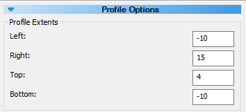
Begin by defining the Profile Extents, located in the Profile Options pane on the left side of the modelling interface.
- Enter the following parameters:
- Left: -10
- Right: 15
- Top: 4
- Bottom: -10

 button to add a borehole.
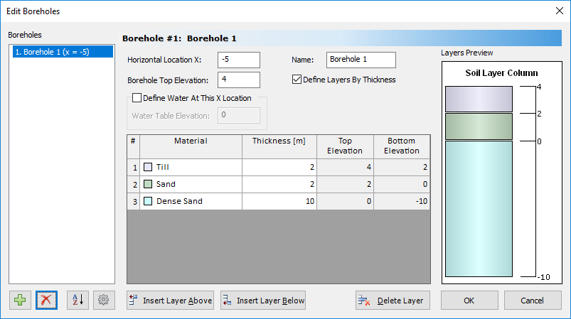
- Horizontal Location X = -5
- Borehole Top Elevation = 4
| # | Material | Thickness (m) |
| 1 | Till | 2 |
| 2 | Sand | 2 |
| 3 | Dense Sand | 10 |
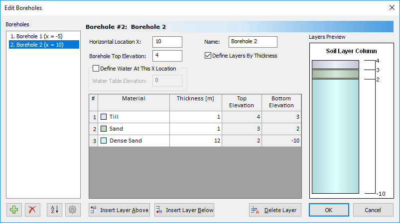
button to add a second borehole.- Horizontal Location X = 10
- Borehole Top Elevation = 4
| # | Material | Thickness (m) |
| 1 | Till | 1 |
| 2 | Sand | 2 |
| 3 | Dense Sand | 12 |
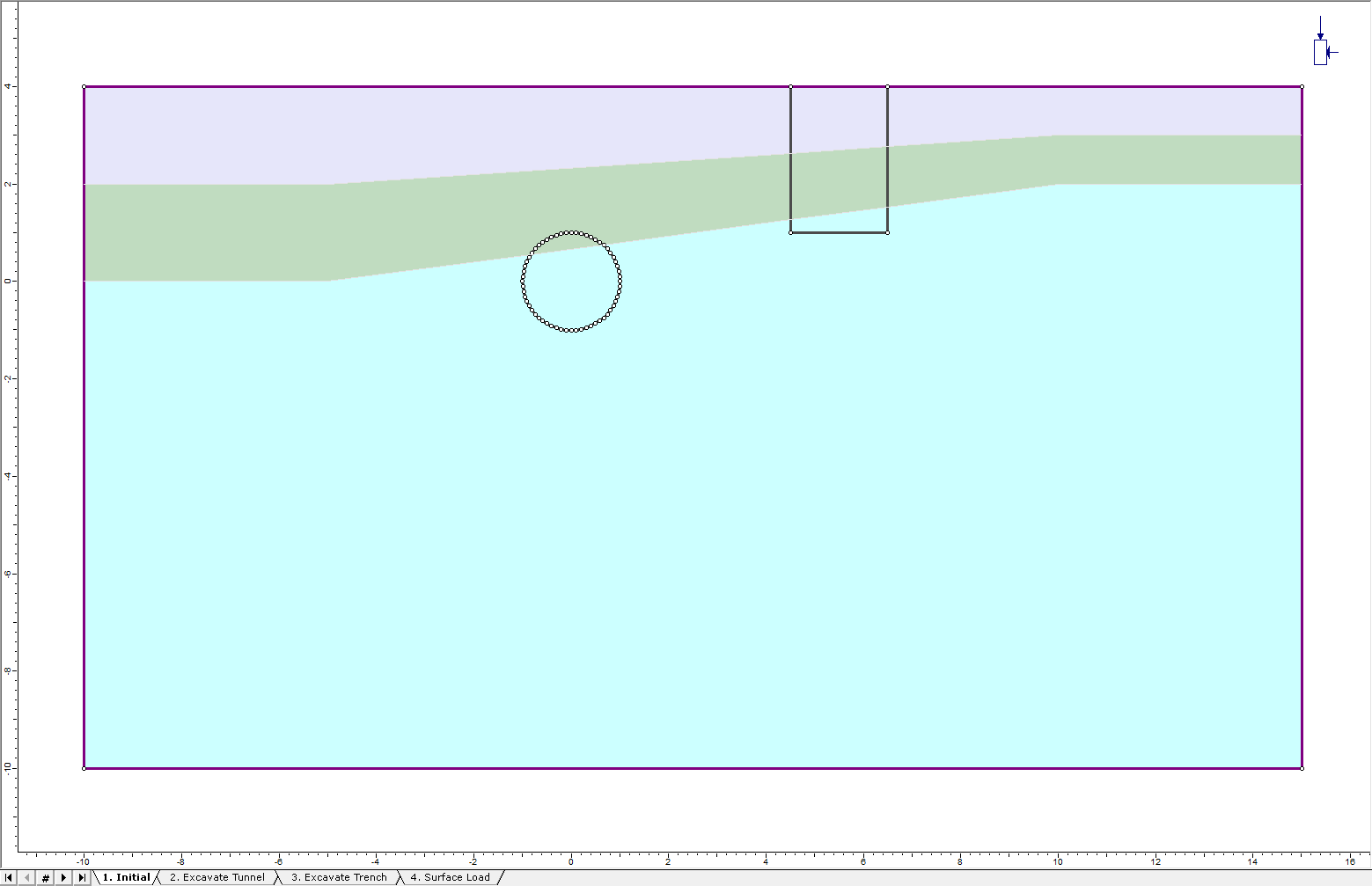
The soil profile should look as follows:

2.3 Entering Geometry
![]()
- Select Boundaries > Add External

The following window will pop up: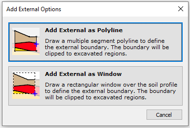
- Select the Add External as Window option.
- Click to select the top left corner of the soil profile boundary and drag to highlight the entire soil profile. Finish the selection by clicking the bottom right corner of the profile. The external boundary has now been created.
Let's add the circular tunnel:
- Select Boundaries > Add Excavation

- Right-click the mouse and select the Circle option from the popup menu.
- Select the Center and radius option, enter Number of Segments = 60 and select OK.
- Enter 0,0 in the prompt line and the circular excavation will be created.
Now enter the rectangular trench:
- Select Boundaries > Add Excavation
- Enter coordinates: (4.5, 4), (4.5, 1), (6.5, 1), (6.5, 4) and enter “c” to close the boundary.
The model should look as follows:
2.4 Assigning Materials
![]()
- Select Properties > Assign Properties

The tunnel will be excavated in Stage 2 and the trench in Stage 3:
- Make sure the Stage 2 tab is selected.
- Select the Excavate button in the Assign dialog.
- Left-click inside the circular tunnel, ensuring to select both sections of material. The contents of the tunnel will now appear white, indicating that the tunnel has been excavated.
- Select the Stage 3 tab.
- Click the left mouse button inside the rectangular trench, ensuring to select all three sections of material. The elements in the trench will disappear, indicating that it is ‘excavated’.
- Close the Assign dialog.
Verify the assignments by selecting each Stage tab in turn and inspecting the model:
- Select Stage 1 – no excavations should be present
- Select Stage 2 – only the tunnel should be excavated.
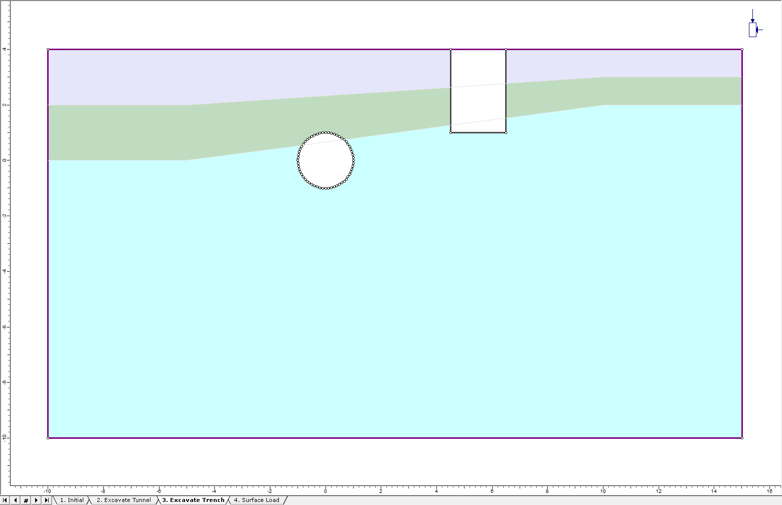
- Select Stage 3 – both the trench and tunnel should be excavated.
The model with both excavations should appear as below (Stage 3):
2.5 Adding a Distributed Load
![]()
Let’s add a uniform distributed load to the ground surface segment above the tunnel.
- Select: Loading > Distributed Load > Add Uniform Load

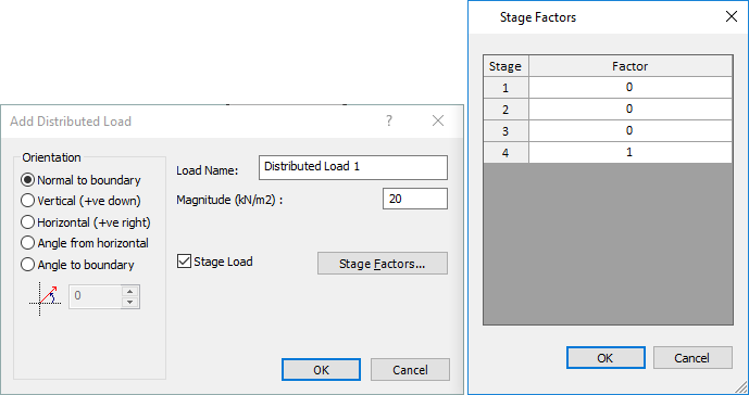
- In the Add Distributed Load dialog, enter a Magnitude = 20 kN/m2. Select the Stage Load check box and select the Stage Factors button.
- In the Stage Factors dialog enter Factor = 0 for Stage 1 , 2, and 3, and Factor = 1 for Stage 4.
- Click OK in both dialogs.
Because of the factors defined, the load will only be applied in the third stage of the analysis and will not exist in the first or second stages. Factor = 1 means the magnitude will be the same as entered in the Add Distributed Load dialog. Factor = 0 means no load will be applied at that stage. Other values of factor can be used to increase or decrease the magnitude of a load at any stage of a model.
Now, select the location of the distributed load on the external boundary:
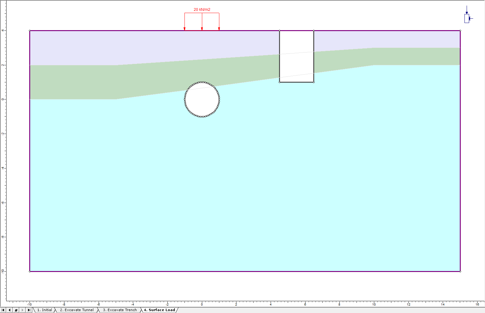
- In the prompt window, enter the following coordinates: (-1, 4) and (1, 4). Press enter to add the load.
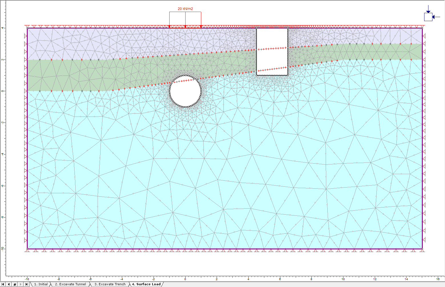
The model should look as follows for Stage 4:
2.6 FIELD STRESS
For most problems involving a ground surface, it is recommended to use a gravity stress field.
- Select: Loading > Field Stress

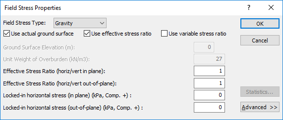
- Enter the above parameters.
- Field Stress Type = Gravity
- Use actual ground surface = YES
- Use effective stress ration = YES
- Effective Stress Ratio (horiz/vert in plane) = 1
- Effective Stress Ratio (horiz/vert out-of-plane) = 1
- Locked-in horizontal stress (in plane) (kPa, Comp. +) = 0
- Locked-in horizontal stress (out-of-plane) (kPa, Comp. +) = 0
2.7 Mesh

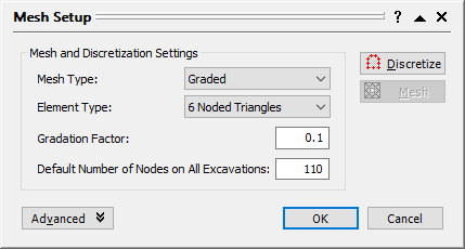
- Select: Mesh > Mesh Setup

- Enter the following mesh parameters:
- Mesh Type = Graded
- Element Type = 6 Noded Triangles
- Gradiation Factor = 0.1
- Default Number of Nodes on All Excavations = 110
The meshed model should look like this:
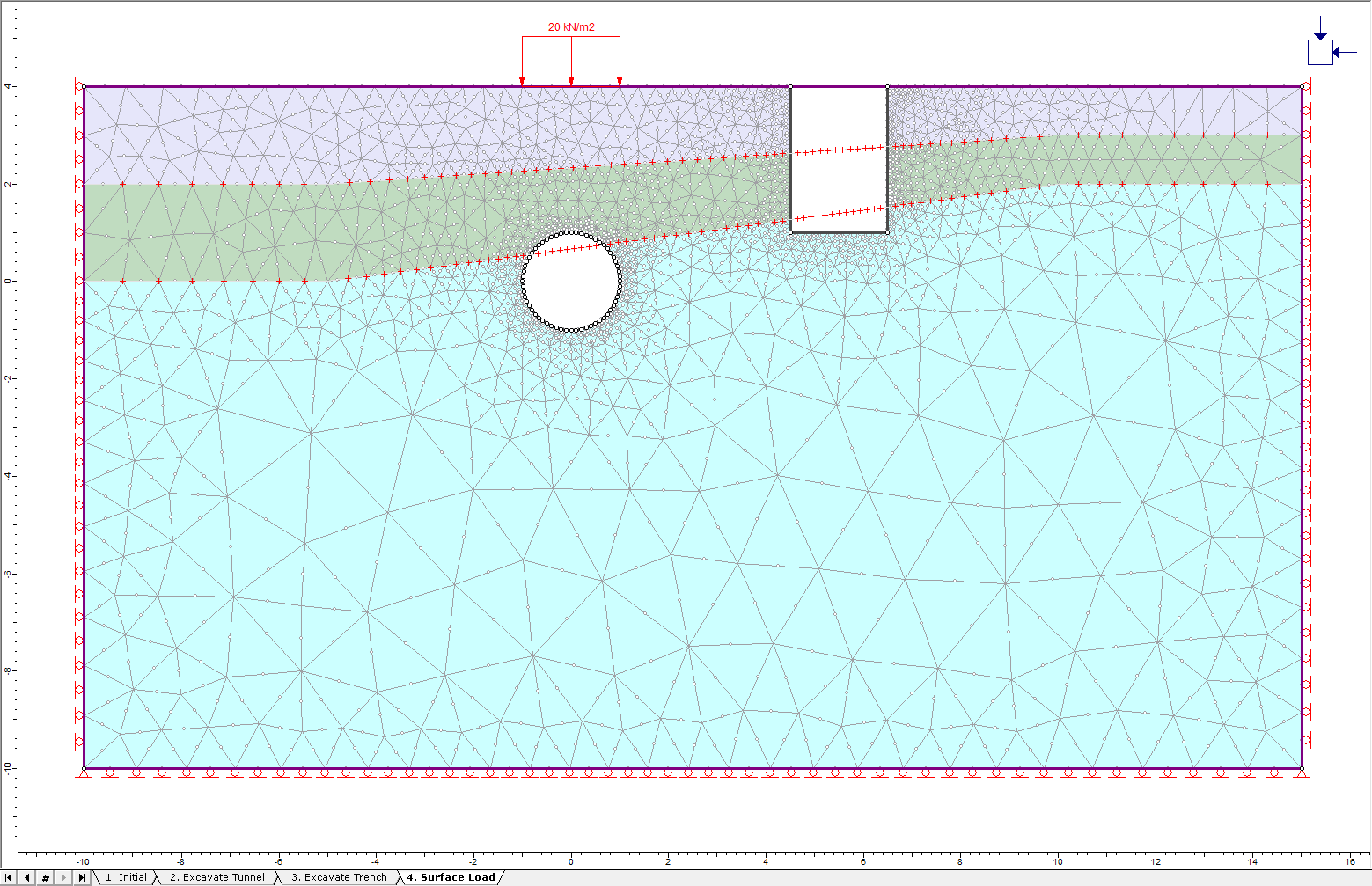
2.8 Boundary Conditions
![]()
Since this is a surface excavation model, we must specify that the ground surface is a free surface. This is done using the Free option in the toolbar or Displacements menu.
- Select: Displacements > Free

- Select boundary segments to free. Use the mouse to select the segments representing the ground surface. Press Enter.
The triangular pin symbols should now be gone from the ground surface indicating that it is free to move without restraint.
Let’s now specify the left and right edges of the external boundary as fixed in the X direction only (i.e. free to move in the Y-direction) and the lower edge as fixed in the Y direction only (i.e. free to move in the X-direction).
- Select: Displacements > Restrain X

- Select boundary segments to restrain in the X direction. Use the mouse to select the left and right edges of the external boundary. Press Enter.
- Select: Displacements > Restrain Y

- Select boundary segments to restrain in the Y direction. Use the mouse to select the bottom edge of the external boundary. Press Enter.
Next, the nodes at the bottom corners have rollers and they should be pinned:
- Select: Displacements > Restrain X,Y

- Right-click the mouse and select Pick by Boundary Nodes from the popup menu. This will change the mode of restraint application from boundary segments to boundary nodes.
- Select the lower left and lower right vertices of the external boundary.
- Press Enter. Triangular pin symbols now replace the roller symbols at these vertices.
The model should look as follows:
3.0 Compute
- Select: Analysis > Compute

4.0 Results and Discussion
- Select: Analysis > Interpret

4.1 Total Displacement
To view the effect of the load on total displacement, the Reference Stage must be set to stage 3, the stage before the addition of the load.
- First, select Total Displacement from the drop-down menu. Now, set the Reference Stage:
- Select: Data > Stage Settings
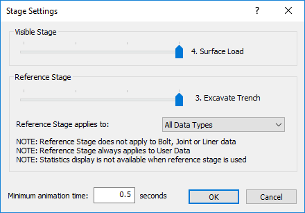
- Set the Reference Stage to 3. Excavate Trench. Press OK.
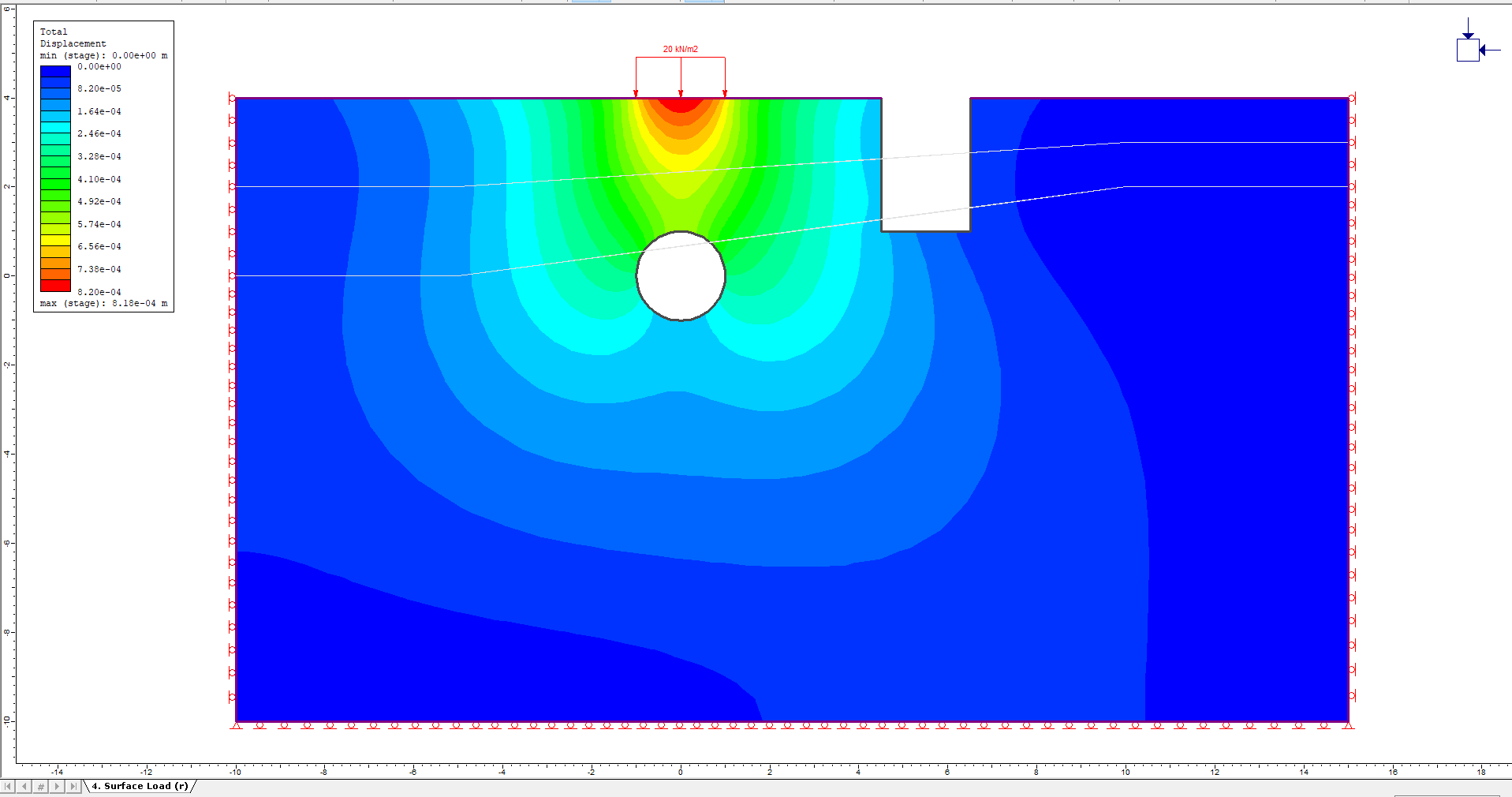
It is apparent that the load has caused significant displacement in all three soil layers. This is because all three layers are sandy soils, and are therefore easily displaced by the surface load.
- Set the Reference Stage back to Not Used.
4.2 Strength Factor
- Select Strength Factor > Ubiquitous Joints from the drop-down menu in the toolbar.
- In the Contour Options dialog, set the number of intervals to 7.
- Select the Stage 4 tab to view the effect of the load. The model should look as follows:
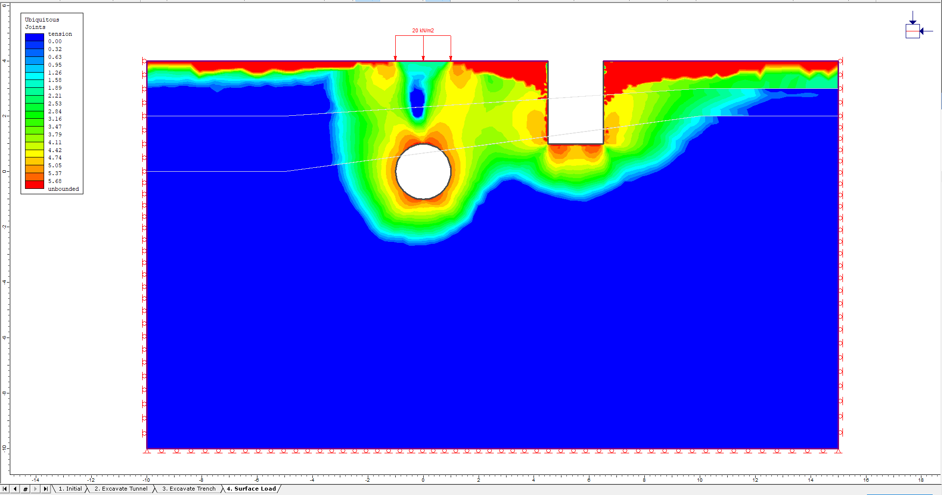
Based on the strength factor contours for this preliminary elastic analysis, it is evident that there is a failure in the material surrounding the tunnel. The orange contours surrounding the tunnel here are less than one, which indicates material failure. It is recommended that additional plastic analyses be performed, along with the addition of support for the trench and the tunnel. This will be left as an optional additional exercise for the user.
This concludes the Profiles and Boreholes tutorial.