Anchored Sheet Pile Wall
1.0 Introduction
In this tutorial, RS2 is used to simulate the construction of an excavation supported by a sheet pile wall anchored with grouted tiebacks. The model consists of two soil layers and two stages of excavation. In the starting model file, project settings have been defined, geometry created (external boundary, material boundary, and a stage boundary), finite element mesh and field stress created, and material properties defined and assigned to the model. The tutorial will proceed to create a sheet pile wall, add grouted tiebacks, and a surcharge to the soil surface behind the wall.
2.0 Constructing the Model
- Select: File > Recent Folders > Tutorial Folder and open the Anchored Sheet Pile Wall (Initial) file
2.1 Sheet Pile Wall
![]()
The sheet pile wall will be installed in Stage 2, so click on the tab to show Stage 2. In this model, the sheet pile wall is sandwiched between two joints. Together, the wall and the joints make up a structural interface.
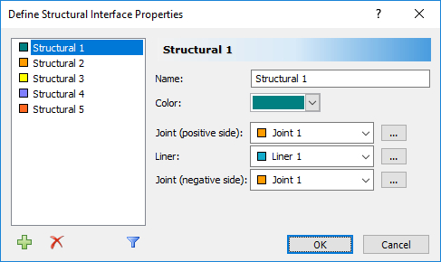
- Right click on the structural interface (dark green line) and select Structural Interface Properties. The dialog displays the default properties of the liner (wall) and the two joints:
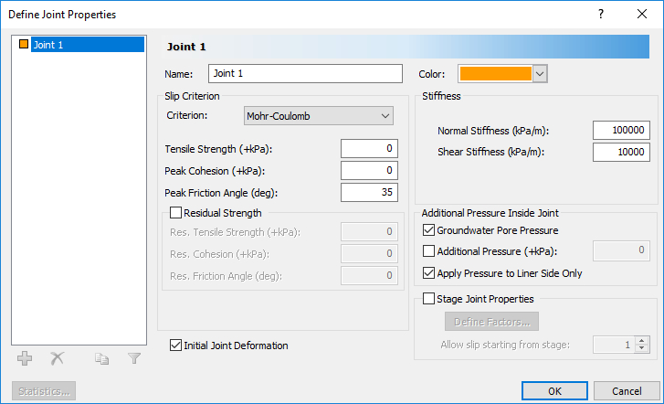
- To modify the properties of the joints, click on the button (...) to the right of Joint 1.
- To allow slip on the joint, change the Slip Criterion to Mohr-Coulomb.
- Leave all other properties as the default properties as shown.
- Click OK to close the dialog and go back to the Structural Interface dialog.
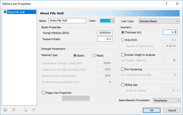
- Click on the button (...) next to Liner 1 to set its properties.
- In the Define Liner Properties dialog:
- Change the name to Sheet Pile Wall.
- Set the thickness to 0.2 m as shown.
2.2 Surcharge

Let’s apply a small surcharge to the soil surface behind the wall.
- Click on the tab for Stage 5.
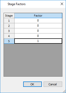
- Select: Loading > Distributed Loads > Add Uniform Load

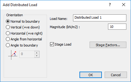
- Set the magnitude to 10 kN/m3 and click the check box for Stage Load. Click on the button for Stage Factors.
- Set all Stage Factors to 0 except for Stage 5 as shown:
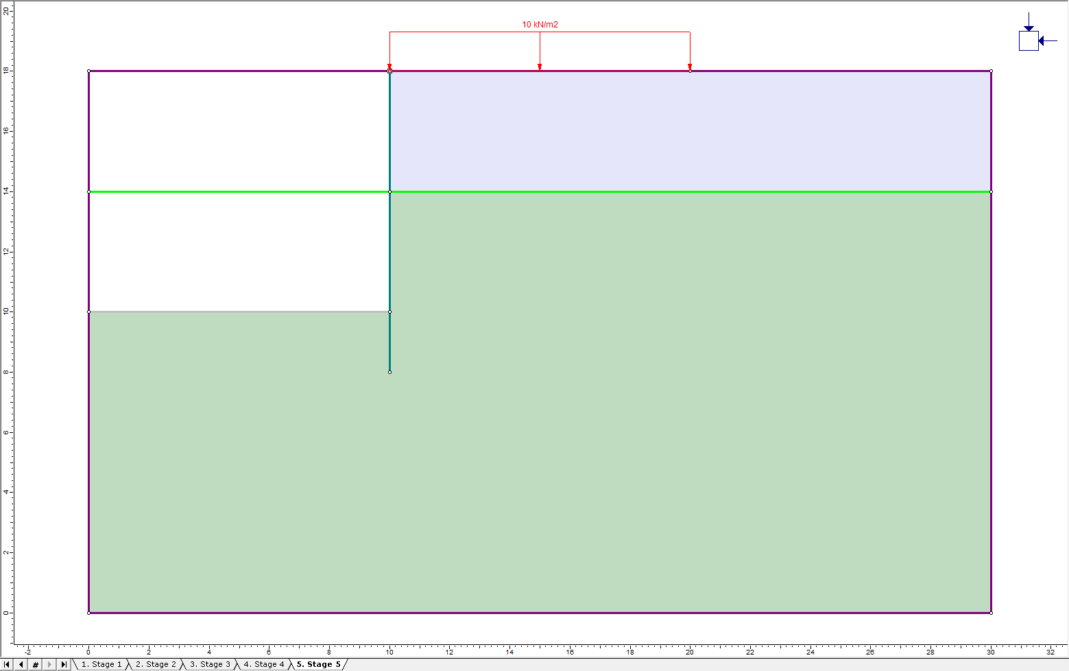
- Click OK to close the dialog. Click OK to close the Add Distributed Load dialog. Select the top boundary just to the right of the excavation and hit Enter to apply the load. The final model for Stage 5 should now look like this:
2.3 Mesh
![]()
- Select: Mesh > Mesh Setup

- Change the Mesh Type to Graded. Change the element type to 3 Noded Triangles and set the number of elements to 120.
- Click the Discretize button, followed by the Mesh button.
- Close the Mesh Setup dialog by selecting the OK button.
2.4 Grouted tiebacks

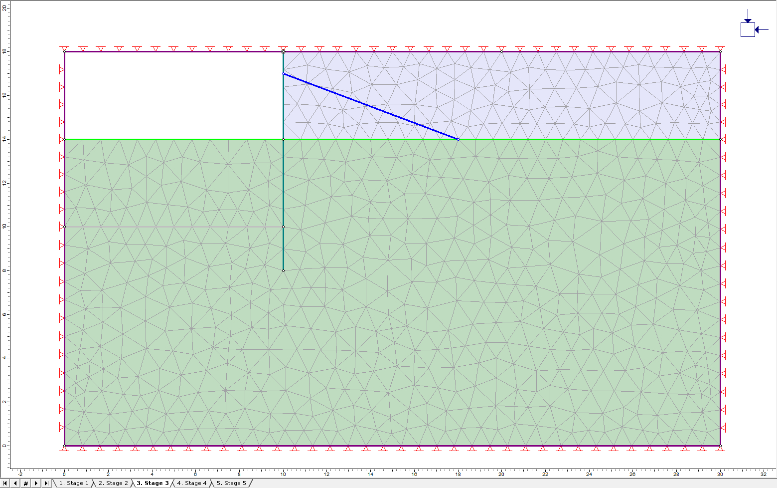
The first tieback will be added in Stage 3 simultaneous with the excavation so click on the tab for Stage 3.
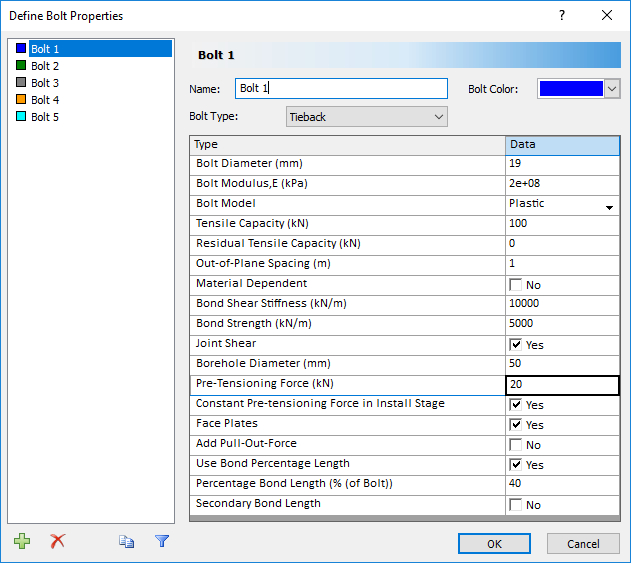
- Select: Support > Add Bolt

- Ensure the Bolt Property is Bolt 1 and ‘Install at Stage’ is 3.
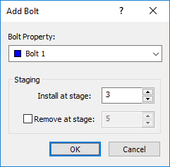
- Click OK to start entering bolt coordinates.
- Enter (10, 17) for the first coordinate.
- Enter the coordinates (18, 14) for the second point.
- Hit Enter to stop entering points.
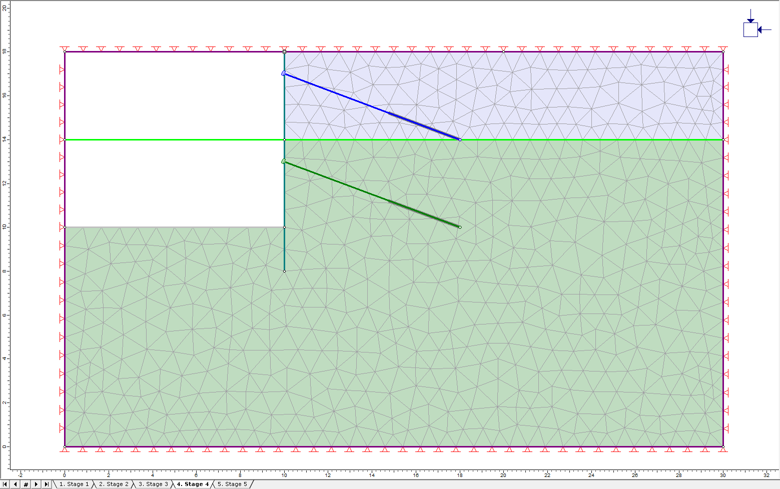
The model will look like this:
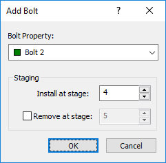
- Enter (10, 13) for the first coordinate.
- Enter the coordinates (18, 10) for the second point.
- Hit Enter to stop entering points.
The model will look like this:
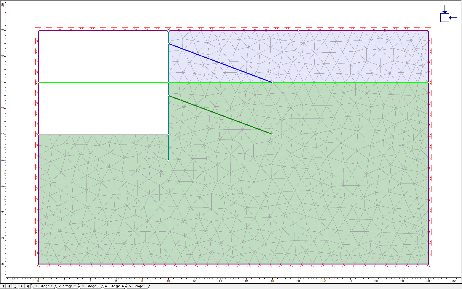

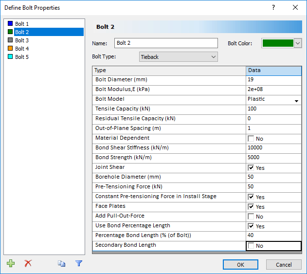
 button and select Bolt 2 to paste the properties to Bolt 2.
Click on the tab for Bolt 2. This bolt material is the same as Bolt 1 except that the Pre-tension force is 50 kN as shown below.
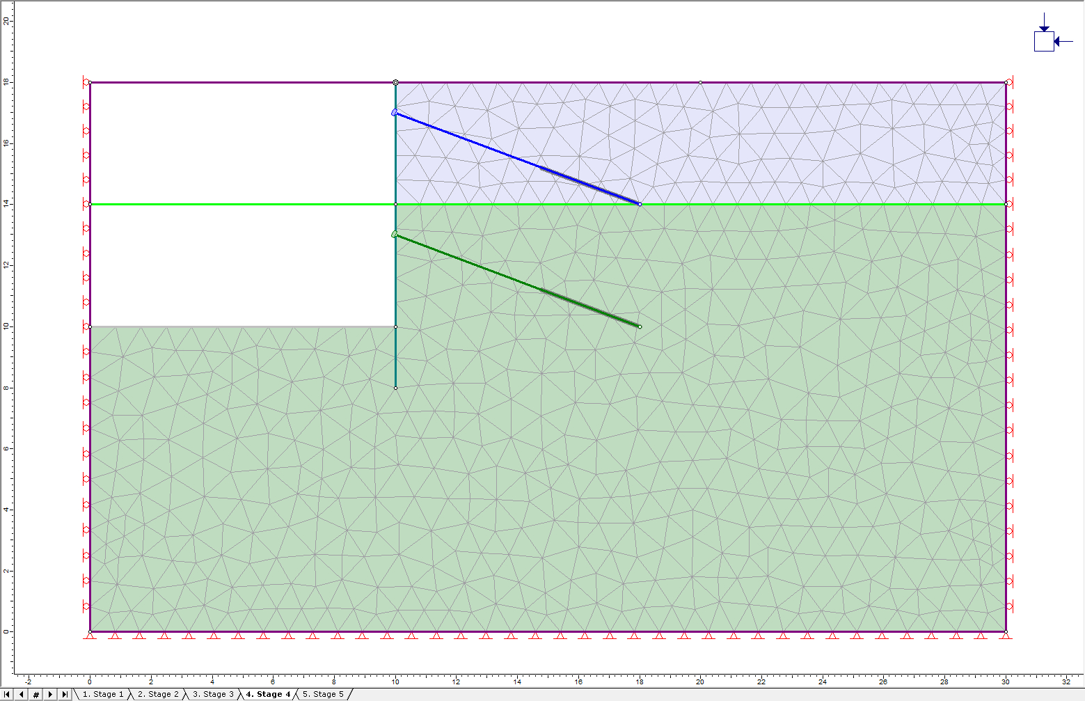
2.5 Restraints

By default, all segments of the external boundary are fixed. Since the top of this model represents the actual ground surface, we need to free the top surface.
- Select: Displacements > Free

- Click on the three sections that make up the top boundary and hit Enter. The fixed boundary conditions have disappeared from the top boundary. The left and right edges should be fixed only in the x-direction to allow vertical movement.
- Select: Displacements > Restrain X

- Select all the sections of the left and right boundaries. These boundaries will now be showing rollers instead of pins.
Finally, we need to re-establish the fixed boundary condition on the bottom corners. - Select: Displacements > Restrain X,Y

- Click on the bottom boundary and hit Enter.
The model should now look like this:
The definition of the model is now complete.
- Select: File > Save As

3.0 Compute
- Select: Analysis > Compute

4.0 Results and Discussion
- Select: Analysis > Interpret

- The maximum stress for Stage 1 will be displayed. Stage 1 only shows the stress due to gravity in the undisturbed material.
- Click the tab for Stage 2 to observe the stress after the installation of the sheet pile wall. There is not much change from Stage 1.
- Change the contours to plot Total Displacement using the drop-down menu in the toolbar.
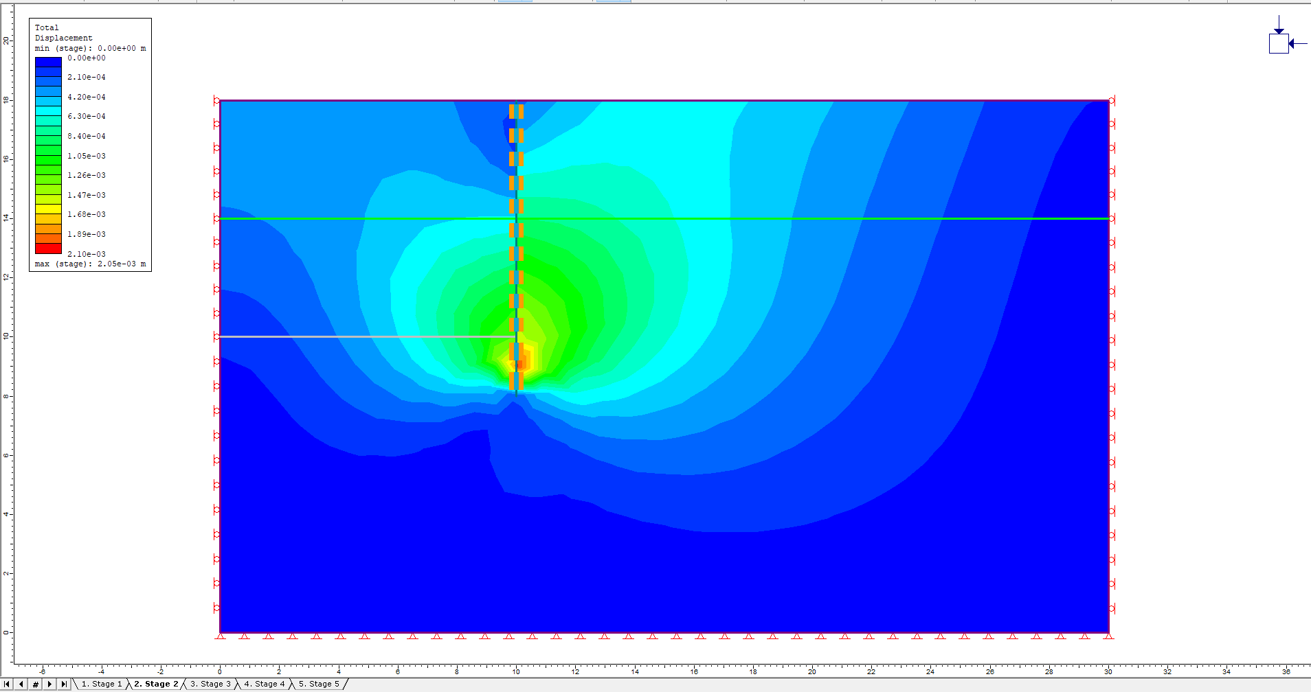
The installation of the sheet pile wall has caused some displacement.
- Click on the tab for Stage 3 and display the deformed boundaries
- Click the Display Deformed Boundaries
 button in the toolbar
There is a slight bulge in the sheet pile wall and the heave of the bottom of the excavation due to removal of the excavated material.
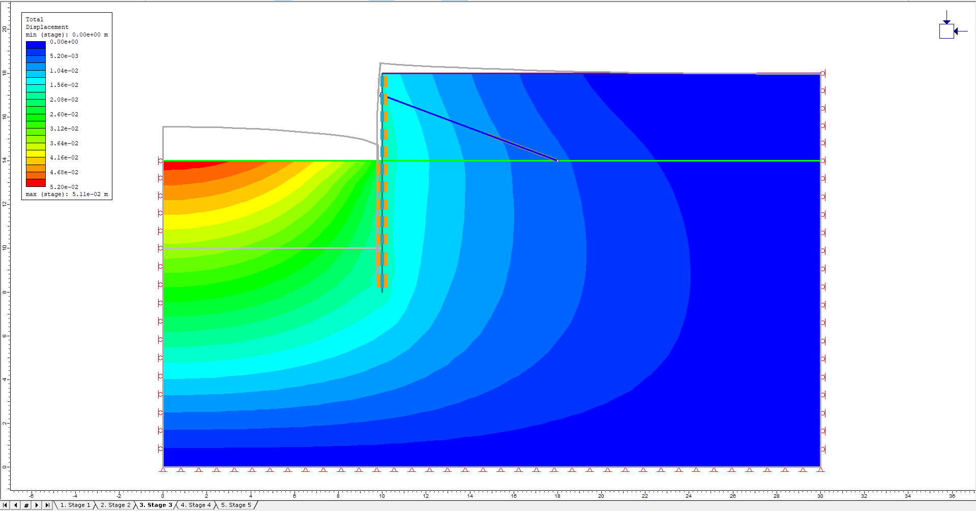
Click the tab for Stage 4 to show the results of the second level of excavation. Here, the bulging of the wall is more pronounced.
To see the actual displacement of the wall, add a query point:
- Select: Query > Add Material Query

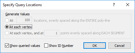
- Select the point at the head of the lower bolt (10,13) and hit enter. Specify the query locations as shown in the dialog below. Set Generate Values to At each Vertex and check the box for Show queried values. Click OK.
The total displacement at the point (in metres) is now visible: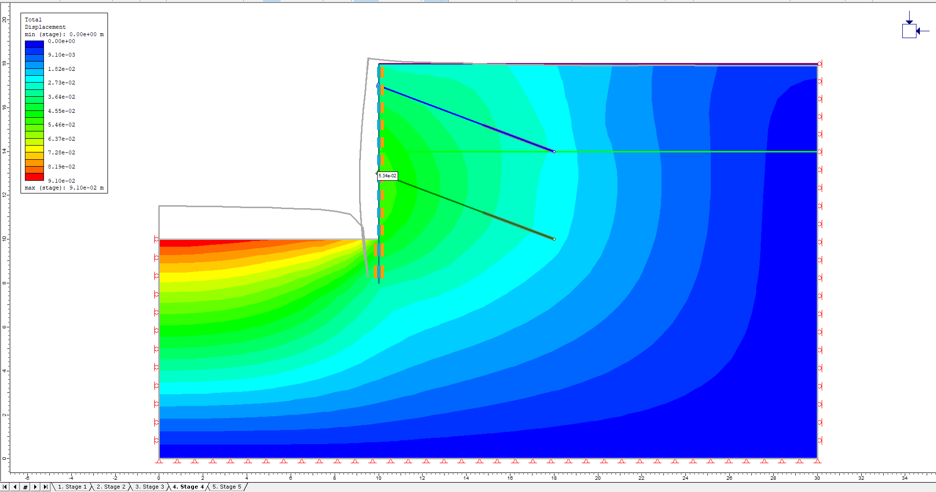
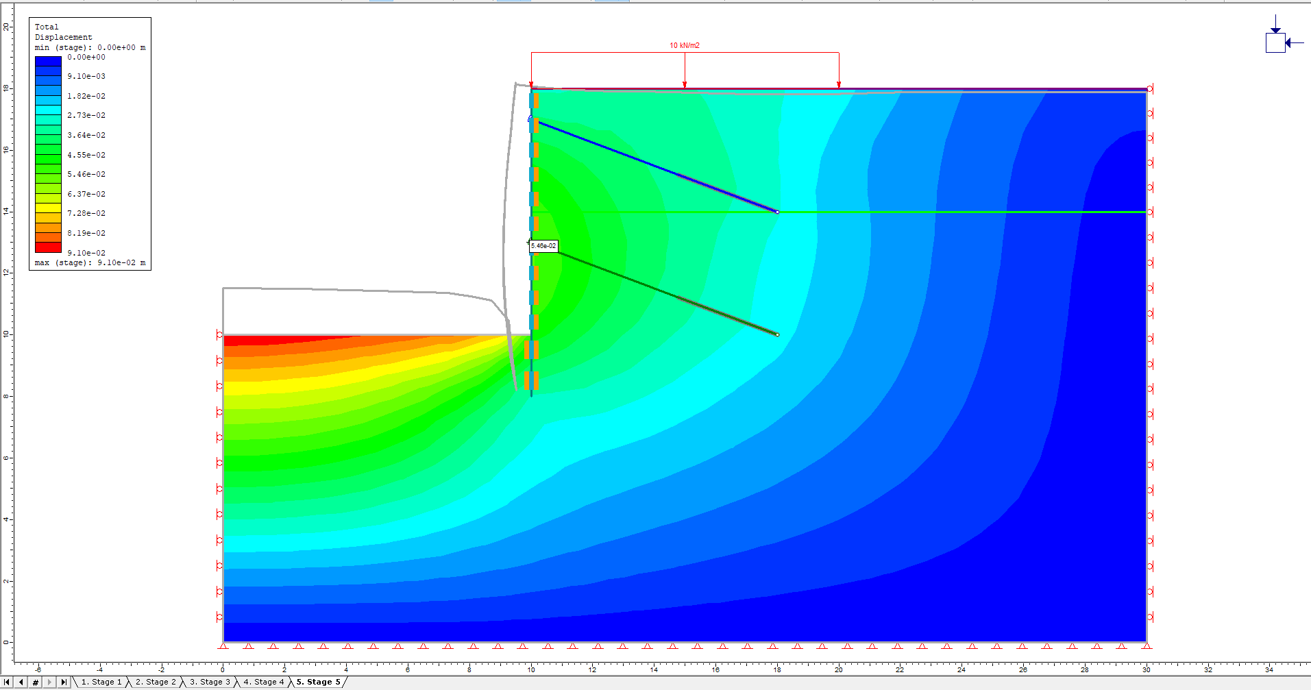
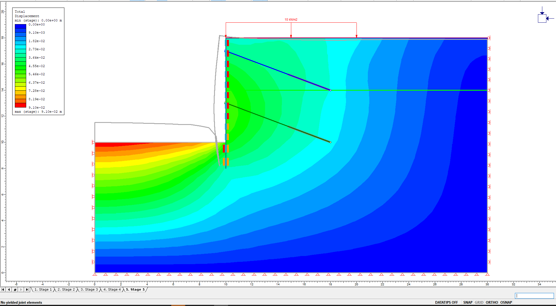
- Click on the tab for Stage 5.
There is an increase in displacement in this stage. If this displacement is too large for project specifications, consider applying a larger pretension force to the bolts. - Delete the query by right clicking on it and choosing Delete Query.
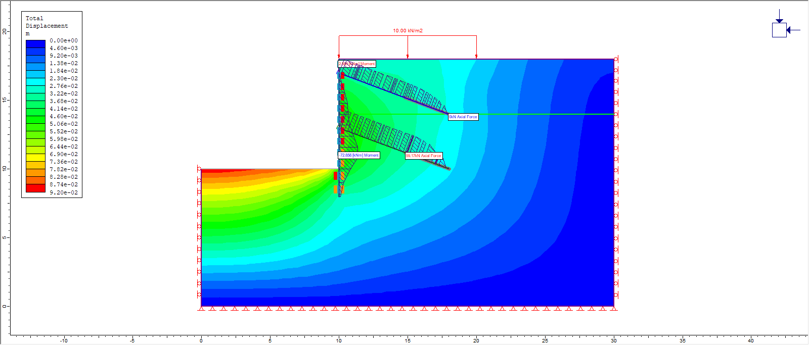
- Right click on one of the bolts and select Show Values > Axial Force. The axial force distribution throughout the bolts is now visible.
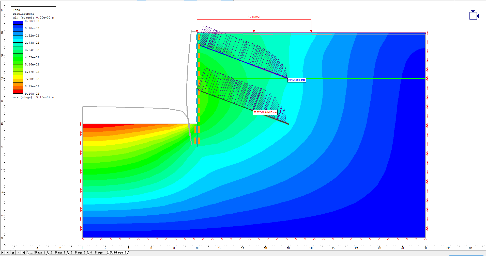
The maximum axial force in the lower bolt (~ 59 kN) is below the tensile strength (100 kN); consider applying a slightly larger pretension without causing bolt failure. - Right click on the bolts and select Show Values > Show Values (all bolts off).
- Click the Display Yielded Joints button on the toolbar.
The wall itself was set to be elastic so it will not exhibit any failure. However, the joint between the liner and soil shows some failure (red elements), indicating that the joint is slipping or separating. It is interesting that there is little slip below the lower bolt, suggesting that the bolt is successfully preventing slip/separation from occurring.
Let’s look at the joint slippage.
- Right click on the wall and select Show Values > Joint Shear Displacement.
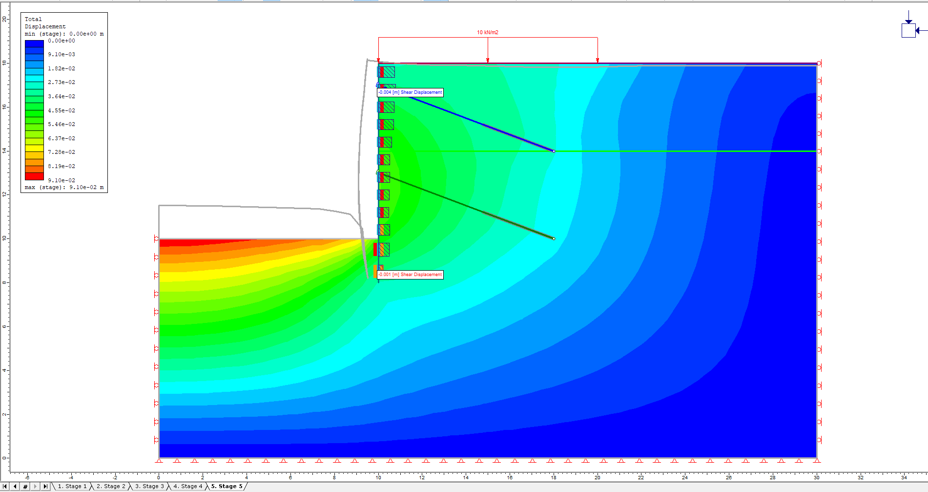
- There are only values at the bottom of the wall. This suggests that there is slip on the left side of the wall rather than on the right. To remedy this, right click on the wall and click Select Support Layer. Click under the Joint heading and select ‘negative side: Joint 1’.
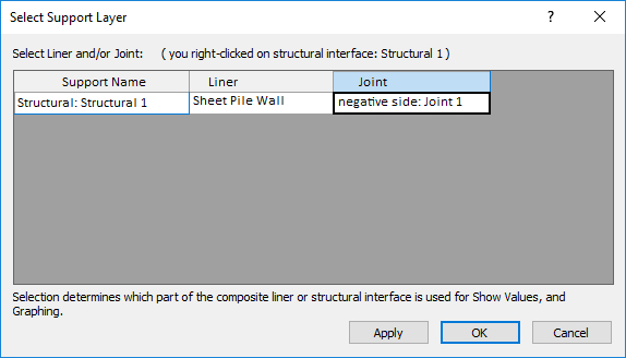
- Click OK to see the shear displacement between the joint and the soil to the right of the wall.
Let’s look at the moments in the sheet pile wall.
- Right click on the wall and select Show Values > Bending Moment. There is a maximum moment of ~71 kNm.
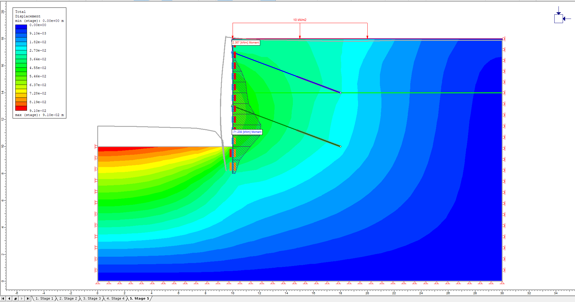
Notice the inflection in the moment curve at the location of the lower bolt.
This concludes the Anchored Sheet Pile Wall tutorial.